Circuit for generating ternary signal

a ternary signal and circuit technology, applied in the direction of logic circuits using specific components, pulse generators, pulse techniques, etc., can solve the problems of complex circuits, disadvantages of miniaturization and cost reduction of the entire device, and achieve cost reduction

Inactive Publication Date: 2008-12-23
COLLABO INNOVATIONS INC
View PDF14 Cites 1 Cited by
  • Summary
  • Abstract
  • Description
  • Claims
  • Application Information

AI Technical Summary

Benefits of technology

[0025]In accordance with this invention, an appropriate ternary signal can be outputted without modifying the system even in a system wherein only a high or low binary input-control signal and a high or low binary reset signal are in use, for example. In the case that the circuit for generating a ternary signal of the present invention is incorporated in a multi-channel driver that is in use for a PDP panel or the like, no systemic change and no circuits for installing the additional input terminal are required. Therefore, a circuit for generating a ternary signal being optimum for miniaturization and cost reduction can be realized.
[0027]In accordance with this invention, an appropriate ternary signal can be outputted with a simple configuration in a system wherein only a high or low binary input-control signal and a high or low binary reset signal are in use, for example. Therefore, a circuit for generating a ternary signal being optimum for miniaturization and cost reduction can be realized.
[0037]In accordance with this invention, a highly reliable circuit for generating a ternary signal that is capable to prevent a reverse current from the first positive potential to the second positive potential from occurring when a first positive potential, a second positive potential and a zero potential are respectively inputted as the high-potential-side power supply, the first low-potential-side power supply and the second low-potential-side power supply by a positive power supply, can be realized.
[0040]The circuit for generating a ternary signal of the present invention has an effect of outputting an appropriate ternary signal without modifying the system even in a system wherein only a binary input-control signal and a binary reset signal are in use, and being optimum for miniaturization and cost reduction.

Problems solved by technology

Therefore, in the system, such as a PDP (Plasma Display Panel) driver or the like, wherein only a high or low binary input-control signal and a high or low binary reset signal are in use, a problem that systemic change such as installation of an additional input terminal or the like is required to generate a ternary signal.
In particular, in the case that the circuit for generating a ternary signal of the prior art is incorporated in a multi-channel driver that is in use for a PDP panel or the like, the circuit is complicated for the purpose of the systemic change to install the additional input terminal.
The complexity of the circuit brings disadvantages for miniaturization and cost reduction of the entire device.

Method used


Image

  • Circuit for generating ternary signal
  • Circuit for generating ternary signal
  • Circuit for generating ternary signal

Examples


first preferred embodiment

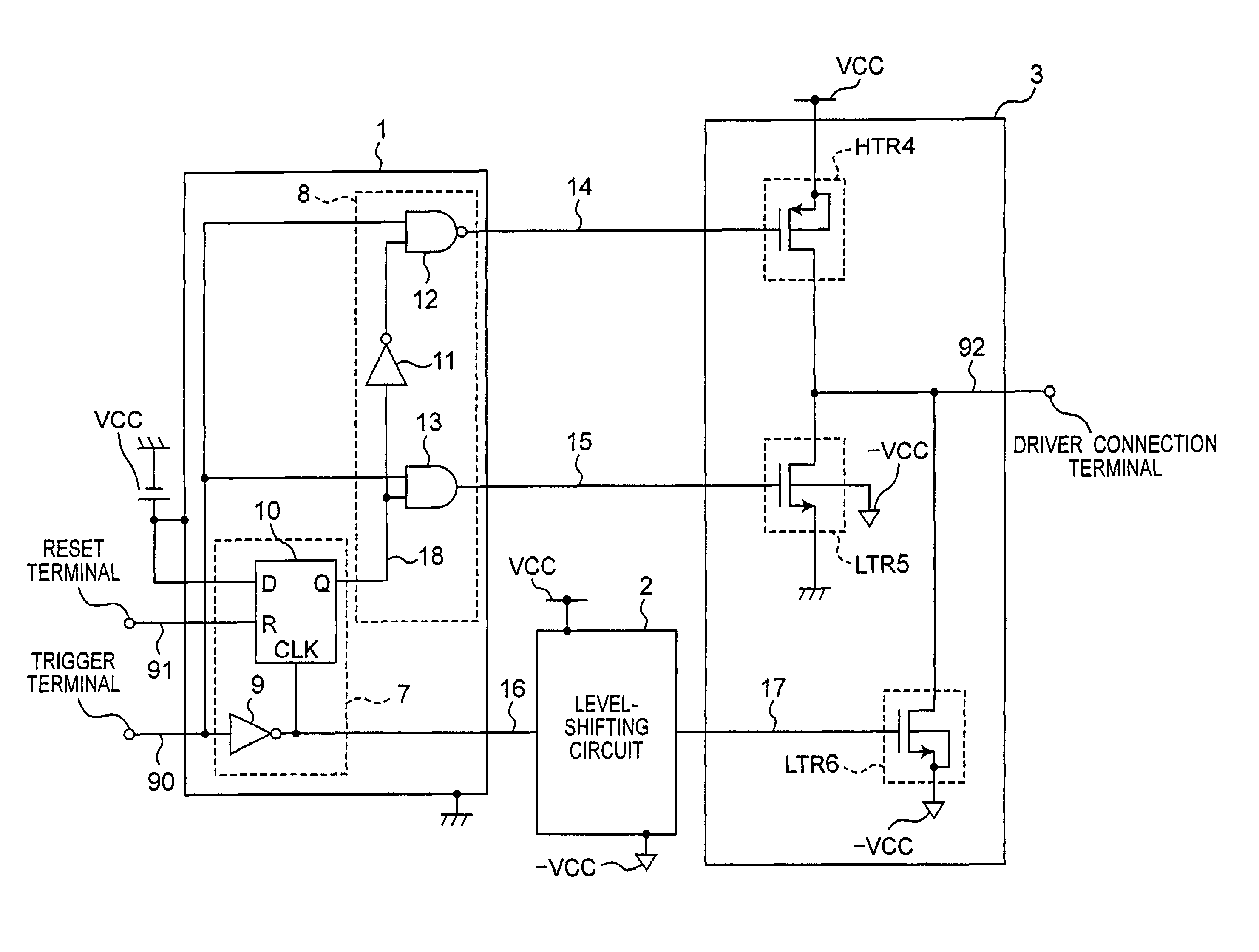
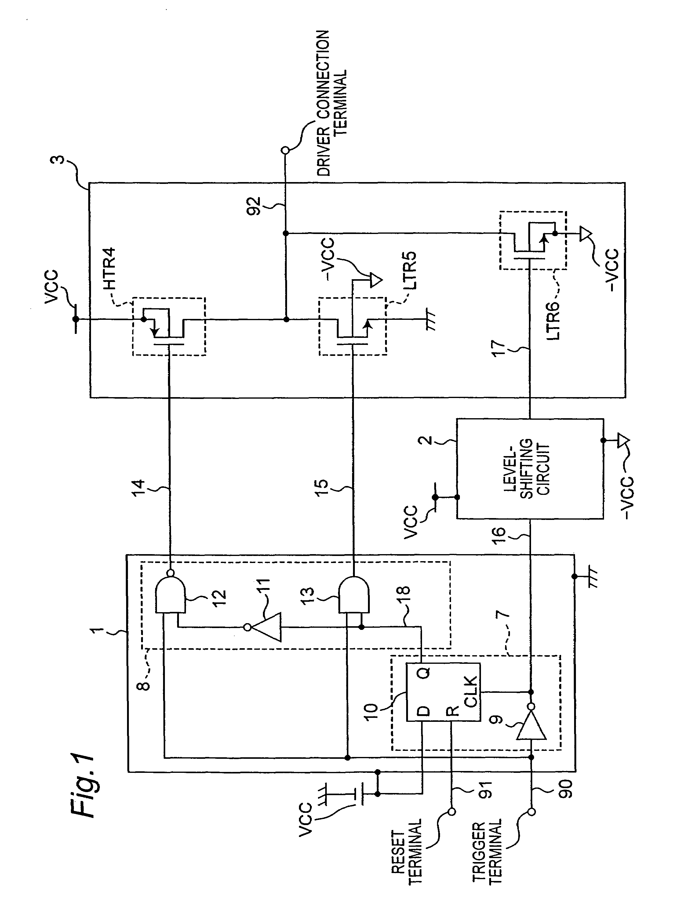
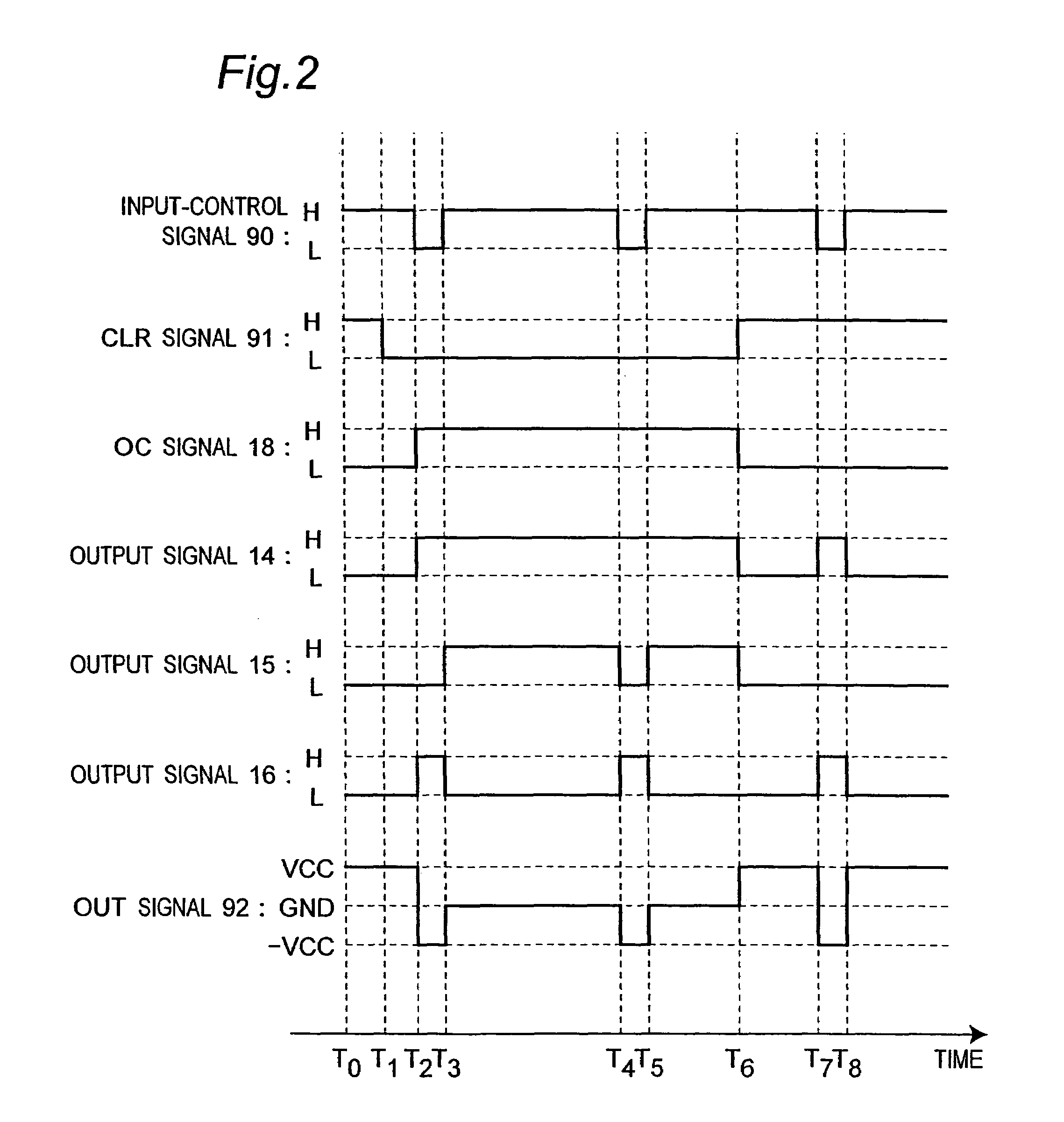
[0051]Referring to FIGS. 1 and 2, a circuit for generating a ternary signal in accordance with a first preferred embodiment of the present invention will be described. FIG. 1 is a circuit diagram showing a configuration of the circuit for generating a ternary signal in accordance with this first preferred embodiment of the present invention. In FIG. 1, the circuit for generating a ternary signal includes a sequential circuit 1, a level-shifting circuit 2, and a ternary output generating circuit 3.

[0052]The sequential circuit 1 includes an edge detecting circuit 7 and a switching circuit 8. The ternary output generating circuit 3 includes a high-potential-side P-channel transistor 4 (hereinafter, referred to as an HTR4), a low-potential-side N-channel transistor 5 (hereinafter, referred to as an LTR5), and a low-potential-side N-channel transistor 6 (hereinafter, referred to as an LTR6).

[0053]The edge detecting circuit 7 of the sequential circuit 1 is composed by a D-type flip-flop c...

second preferred embodiment

[0085]Referring to FIGS. 3 and 4, a circuit for generating a ternary signal in accordance with a second preferred embodiment of the present invention will be described. FIG. 3 is a circuit diagram showing a configuration of the circuit for generating a ternary signal in accordance with this second preferred embodiment of the present invention. In FIG. 3, the circuit for generating a ternary signal in accordance with this second preferred embodiment of the present invention is different from that of the first preferred embodiment of the present invention shown in FIG. 1 in that a level-shifting circuit 25 is provided instead of the level-shifting circuit 2, a ternary output generating circuit 27 is provided instead of the ternary output generating circuit 3, and a level-shifting circuit 26 is added.

[0086]In the circuit for generating a ternary signal of the prior art shown in FIG. 7 and in the circuit for generating a ternary signal in accordance with the first preferred embodiment s...

third preferred embodiment

[0108]Referring to FIGS. 5 and 6, a circuit for generating a ternary signal in accordance with a third preferred embodiment of the present invention will be described. FIG. 5 is a circuit diagram showing a configuration of the circuit for generating a ternary signal in accordance with this third preferred embodiment of the present invention. In FIG. 5, the circuit for generating a ternary signal in accordance with this third preferred embodiment of the present invention is different from that of the first preferred embodiment of the present invention shown in FIG. 1 in that a sequential circuit 35 is provided instead of the sequential circuit 1, the level-shifting circuit 2 is removed, level-shifting circuit 40 and 41 are added, and a ternary output generating circuit 42 is provided instead of the ternary output generating circuit 3.

[0109]In the circuit for generating a ternary signal of the prior art shown in FIG. 7 and in the circuit for generating a ternary signal in accordance w...


PUM


Abstract

A circuit for generating a ternary signal that receives a binary input-control signal and a binary reset signal and outputs a ternary signal. The circuit includes first to third transistors, each source terminal thereof is respectively connected to the three power supplies, and a sequential circuit that outputs control signals controlling the transistors. The sequential circuit outputs control signals that make the first and the third transistors be switched in a complementary manner in an initial state, and make the second and the third transistors be switched in a state that it is released from the initial state.

Description

BACKGROUND OF THE INVENTION[0001]1. Field of the Invention[0002]The present invention relates to a circuit for generating a ternary signal which receives a binary input-control signal and a binary reset signal and outputs a ternary signal from an output terminal, and in particular, relates to a circuit for generating a ternary signal which includes at least three transistors respectively controlled by different control signals.[0003]2. Description of the Related Art[0004]In recent years, a circuit for generating a ternary signal that outputs an output signal having three levels is for use in a multi-channel driver being in use for a flat-panel display. As a circuit for generating a ternary signal of a prior art, disclosed in FIGS. 2 and 3 of the Japanese patent laid-open publication No. 7-114361 is a circuit for generating a ternary signal having two level-shifting circuits and complementary metal-oxide semiconductor transistors of a PMOS and an NMOS.[0005]FIG. 7 is a circuit diagra...

Claims


Application Information

Patent Timeline
Patent Type & Authority Patents(United States)
IPC IPC(8): H04L25/34
CPCH03K3/00H03K17/00H03K17/693
Inventor KANEDA, JINSAKUMAEJIMA, AKIHIROMATSUNAGA, HIROKIMAEDA, EISAKUANDO, HIROSHI
Owner COLLABO INNOVATIONS INC
Why Eureka
Try Eureka