Self-contained thermal actuator

Active Publication Date: 2008-12-30
ROSTRA VERNATHERM
View PDF10 Cites 17 Cited by
  • Summary
  • Abstract
  • Description
  • Claims
  • Application Information

AI Technical Summary

Benefits of technology

[0006]The inventive thermal actuator eliminates the separately manufactured guide member of the typical actuator design. Further, a simple O-ring seal replaces the more complex diaphragm seal and its associated plug. One benefit of the inventive design is a more direct force delivery from the expanding wax to the piston due to elimination of the intervening diaphragm seal and plug of the prior art. O-ring seals are standard elements whose mechanical behavior and sealing characteristics are well understood. Therefore, an effective wax containment seal can be accomplished at reduced cost compared to the previous diaphragm type seal.
[0008]The invention is particularly useful in applications requiring a miniature, self-contained thermal actuator. The disclosed thermal actuator configuration provides a simple, durable, reliable and relatively inexpensive thermally responsive actuator.

Problems solved by technology

The necessity for an external biasing member complicates assemblies utilizing the wax filled thermal actuator and precludes provision of a self-contained actuator of this type.

Method used


Image

  • Self-contained thermal actuator
  • Self-contained thermal actuator
  • Self-contained thermal actuator

Examples


Embodiment Construction

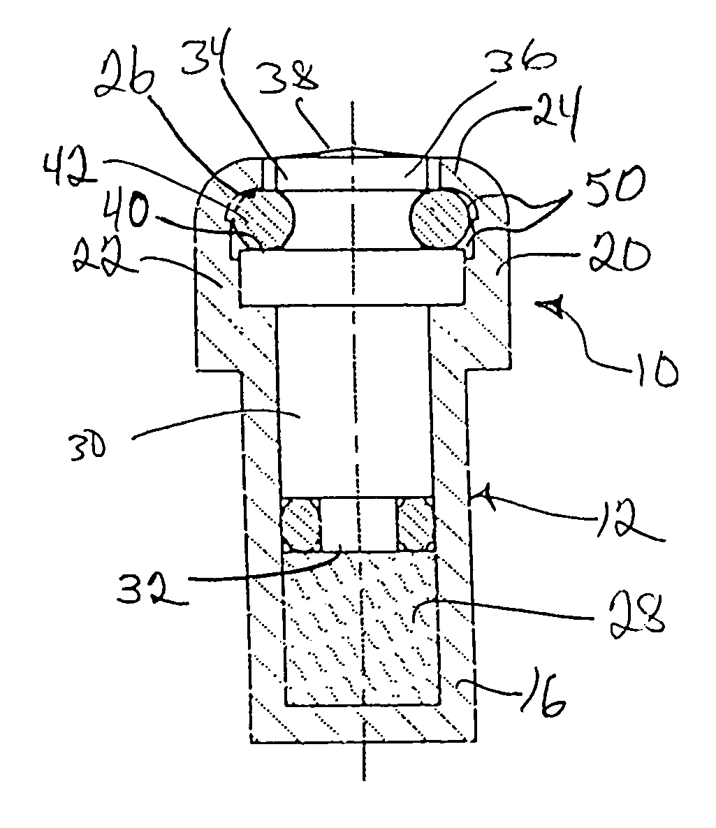
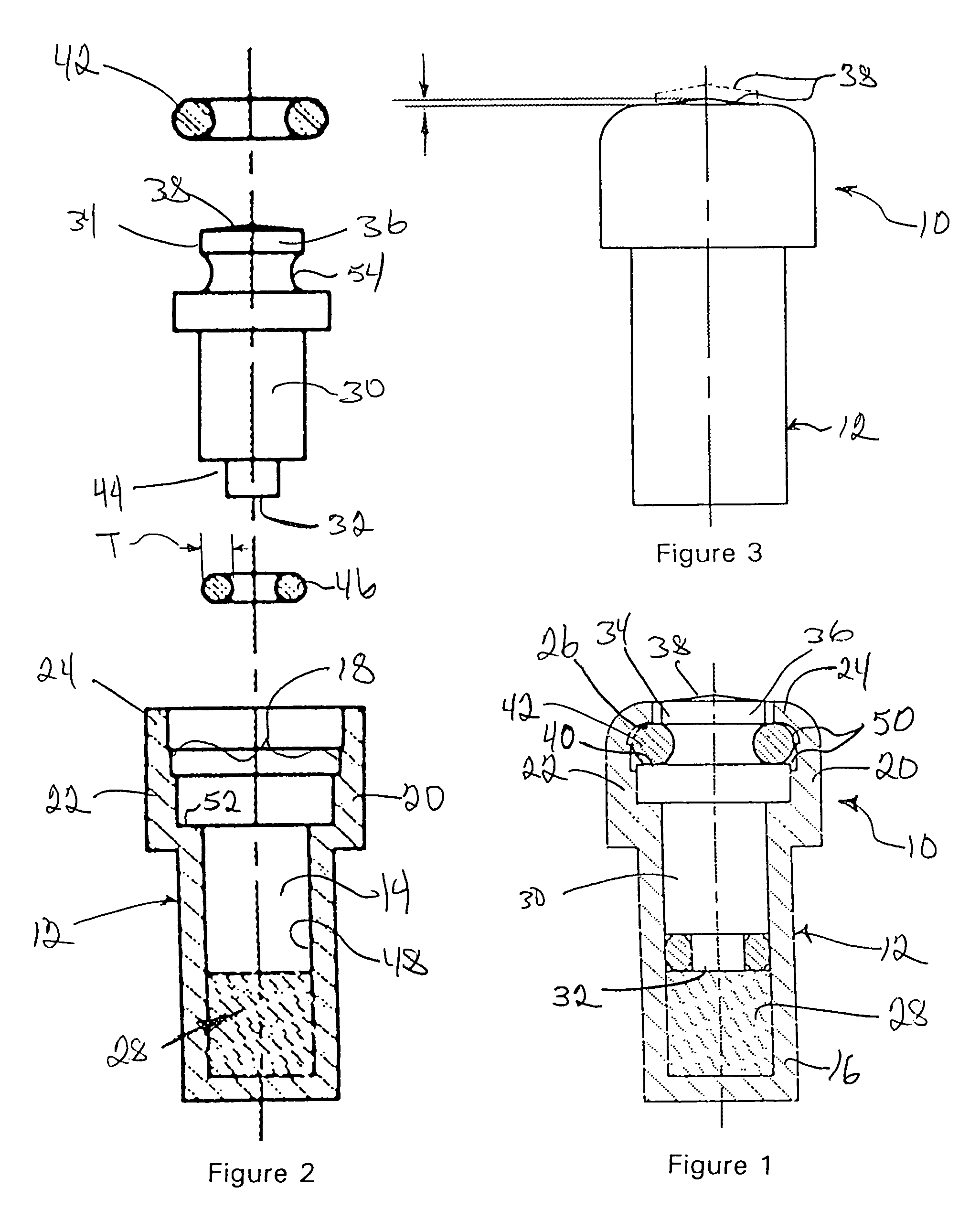
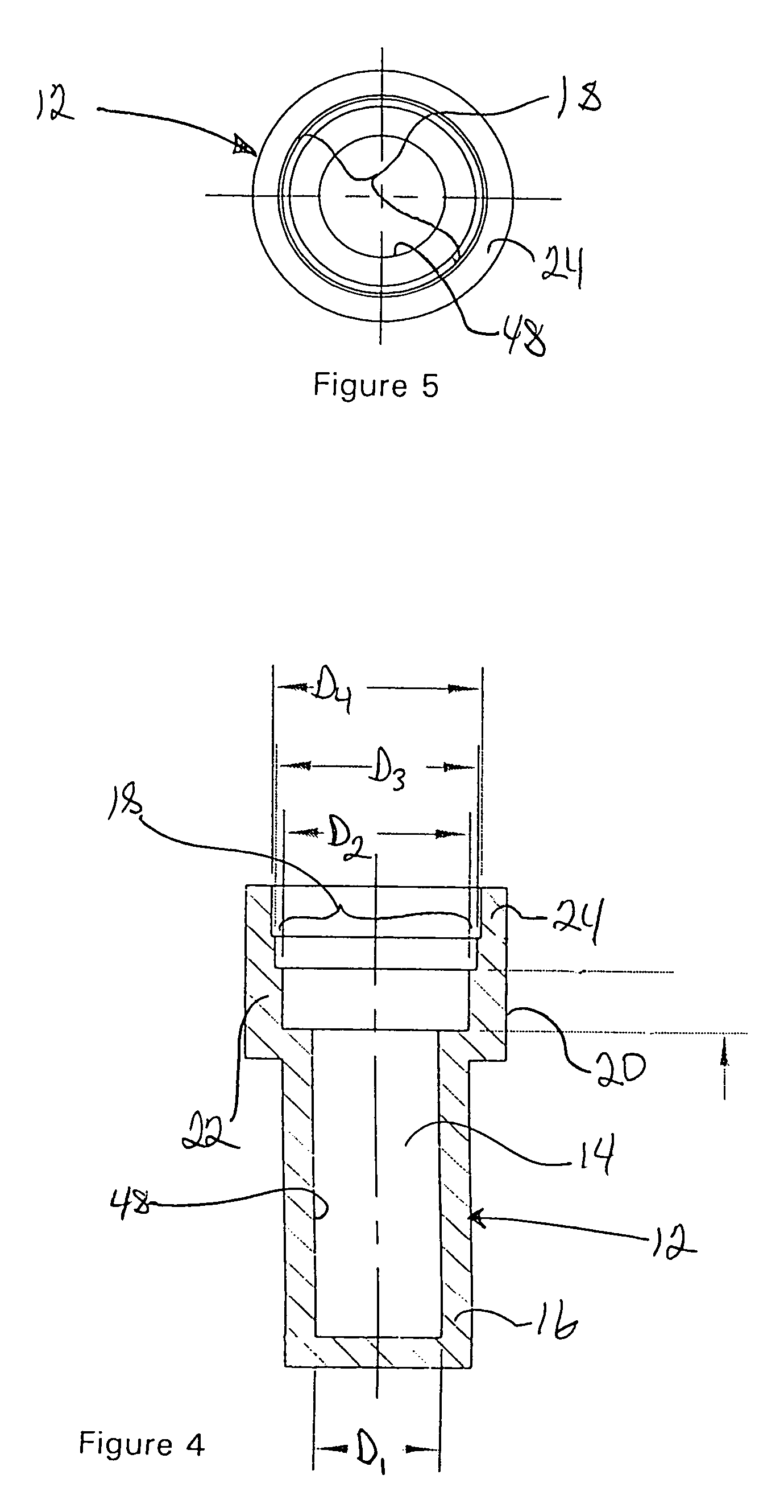
[0022]A first embodiment of a thermal actuator according to aspects of the present invention will now be described with reference to FIGS. 1-7. The thermal actuator 10 includes a rigid cup 12 defining a longitudinal bore 14 extending from a closed bottom portion 16 of the cup to an opening 18 defined by a top portion 20 of the cup. A wall 22 surrounds the opening 18 at the top of the cup. As best seen in FIGS. 2 and 4, the bore 14 in the cup may be a stepped bore having a first diameter D1 at the bottom portion 16 of the cup and expanding in stepwise fashion D2, D3, D4 as the bore progresses toward the open top portion 20 of the cup. The largest diameter D4 of the bore 14 thins the cup wall 22 to form a lip 24. After the parts shown in FIG. 2 are assembled together and installed within the cup as shown in FIG. 1, the lip 24 is bent (formed) inwardly to define a first annular shoulder 26. The inwardly formed lip 24 retains the parts within the cup 12 as a substantially sealed, self-c...


PUM


Abstract

A self-contained thermal actuator positions the piston return member inside the actuator cup. The inventive configuration eliminates the guide and diaphragm seal that closed the open end of the wax filled cup in the typical thermal actuator configuration. The piston and an O-ring seal seated in an annular recess defined by the piston contain the thermally responsive wax. A return member within the cup and engaged between axially spaced, radially overlapping shoulders on the cup and piston biases the piston toward its pre-actuation position. The return member may be a spring or an elastomeric O-ring that also seals the thermal actuator against intrusion of contaminants from the use environment. The piston is closely received in the cup for guided axial reciprocation therein.

Description

BACKGROUND OF THE INVENTION[0001]1. Field of the Invention[0002]The present invention relates to a thermally actuated control device, particularly of the type wherein a thermally responsive wax generates a force to move an actuator in the form of a push rod or the like.[0003]2. Description of the Related Art[0004]Actuators of this type are often used for thermal control valves, such as described in U.S. Pat. Nos. 2,873,633, 4,036,433 and 5,176,317. Typically, such actuators are designed to produce a predetermined actuating movement in response to a change in temperature. One typical configuration for a thermal actuator includes a rigid cup filled with the thermally responsive wax, a resilient diaphragm wax seal covering the wax, a rigid guide member covering the diaphragm wax seal, and an actuator rod or piston received in the guide member to bear on a plug extending from the wax seal. An increase in temperature ΔT causes the thermally responsive wax to expand, generating a force ag...

Claims


Application Information

Patent Timeline
IPC IPC(8): G05D23/12
CPCF03G7/06
Inventor LAMB, KEVIN W.VOYTEK, EDWARD A.PISCITELLI, DAVID
Owner ROSTRA VERNATHERM
Why Eureka
Try Eureka