Liquid ejecting apparatus

a technology of liquid ejection and ejection chamber, which is applied in the direction of printing, other printing apparatus, etc., can solve the problems of rapid loss of kinetic energy, unsatisfactory etc., and achieve the effect of not deteriorating the performance of the absorbing member

Inactive Publication Date: 2008-12-30
SEIKO EPSON CORP
View PDF25 Cites 0 Cited by
  • Summary
  • Abstract
  • Description
  • Claims
  • Application Information

AI Technical Summary

Benefits of technology

[0015]To solve the above-described problem, a first embodiment of the present invention provides a liquid injecting apparatus. The liquid injecting apparatus includes: a liquid ejection head including a nozzle plate having openings, for discharging liquid into a recording medium; an absorbing member disposed further than the recording medium on the orbit of the liquid discharged from the nozzle plate and having an absorbing surface for absorbing the liquid which has not applied on the recording medium; an waste liquid absorbing member having a capillarity higher than that of the absorbing member and being in contact with the absorbing member on a connecting surface different from the absorbing surface, for sucking in the liquid absorbed in the absorbing member; and a potential difference generating means for generating a potential difference between the absorbing surface and the connecting surface of the absorbing member and for attracting the solute of the liquid from the absorbing surface to the connecting surface through electrophoresis. Thereby the solute such as dye and pigment which is dispersed with a charge in the liquid can be actively moved toward the portion in contact with the waste liquid absorbing member in the interior of the absorbing member. Accordingly, the solute is not intensively accumulated around the surface of the absorbing member so that the performance of the absorbing member is not deteriorated.
[0016]In the liquid ejection apparatus according to another embodiment of the present invention, one end of the potential difference generation means connects to a connecting surface side electrode abutted against the absorbing member around the connecting surface, for positioning the connecting surface. Thereby the positioning and the good electrical connection of the absorbing member can be achieved with a simple configuration.
[0017]In the liquid ejection apparatus according to another embodiment of the present invention, the other end of the potential difference generation means connects to an absorbing surface side electrode disposed adjacent to the absorbing surface. Thereby the potential of the surface of the absorbing member is clearly defined, so that the solute can be most effectively sucked.

Problems solved by technology

If the liquid which has not been applied to the recording medium is left, the liquid ejection apparatus itself, an undesired region of the recording medium and the hands of the user may be smeared.
Since the mass of such micro droplets is extremely small, the kinetic energy is rapidly lost due to the viscosity resistance of atmosphere as soon as those eject out in the air.
Therefore, a part of the droplets which has not been applied on the recording medium loses the kinetic energy before arriving at the absorbing material.
Additionally, if the ejection velocity is increased, the remarkably micro droplets referred to as a satellite ink, which are generated when the droplets are released from the nozzle plate is easily generated, undesirably.
However, the liquid ejected in the flushing is consumed only for the flushing and does not contribute to record the recording medium.
Additionally, since the time required for the flushing causes the throughput of a recording operation to decrease, the liquid ejects from all the nozzles within a short time when the flushing is performed.
In such flushing operation, the large amount of satellite ink is generated.
Here, when the aerosols deposit on a convey path of the recording medium, such as a platen, the recording medium which is subsequently conveyed is polluted.
Additionally, when the aerosols are deposited on an electric circuit, a linear scale or various optical sensors in the liquid ejection apparatus, it may cause the malfunction of the apparatus in itself.
Further, when the user touches the sections on which the aerosols are deposited, the hands of the user are polluted.
However, since the amount of liquid applied on the platen is not constant, it unexpectedly takes time to discharge the liquid to the outside of the platen, so that the liquid may sometimes remain oh the platen.
In this case, it is impossible to prevent mists from generating.
However, the volatile component of the held liquid is evaporated around the surface of the absorbing member, so that the nonvolatile component is intensively accumulated adjacent to the surface of the absorbing member.
Therefore, the absorbing member is clogged so that the desired function of the absorbing member, which receives the liquid without generating any mist may be lost.
Thereby the recording medium subsequently provided may be polluted.

Method used


Image

  • Liquid ejecting apparatus
  • Liquid ejecting apparatus
  • Liquid ejecting apparatus

Examples


Embodiment Construction

[0040]Hereinafter, the present invention will now be described through referred embodiments. The embodiments do not limit the invention according to claims and all combinations of the features described in the embodiments are not necessarily essential to means for solving the problems of the invention.

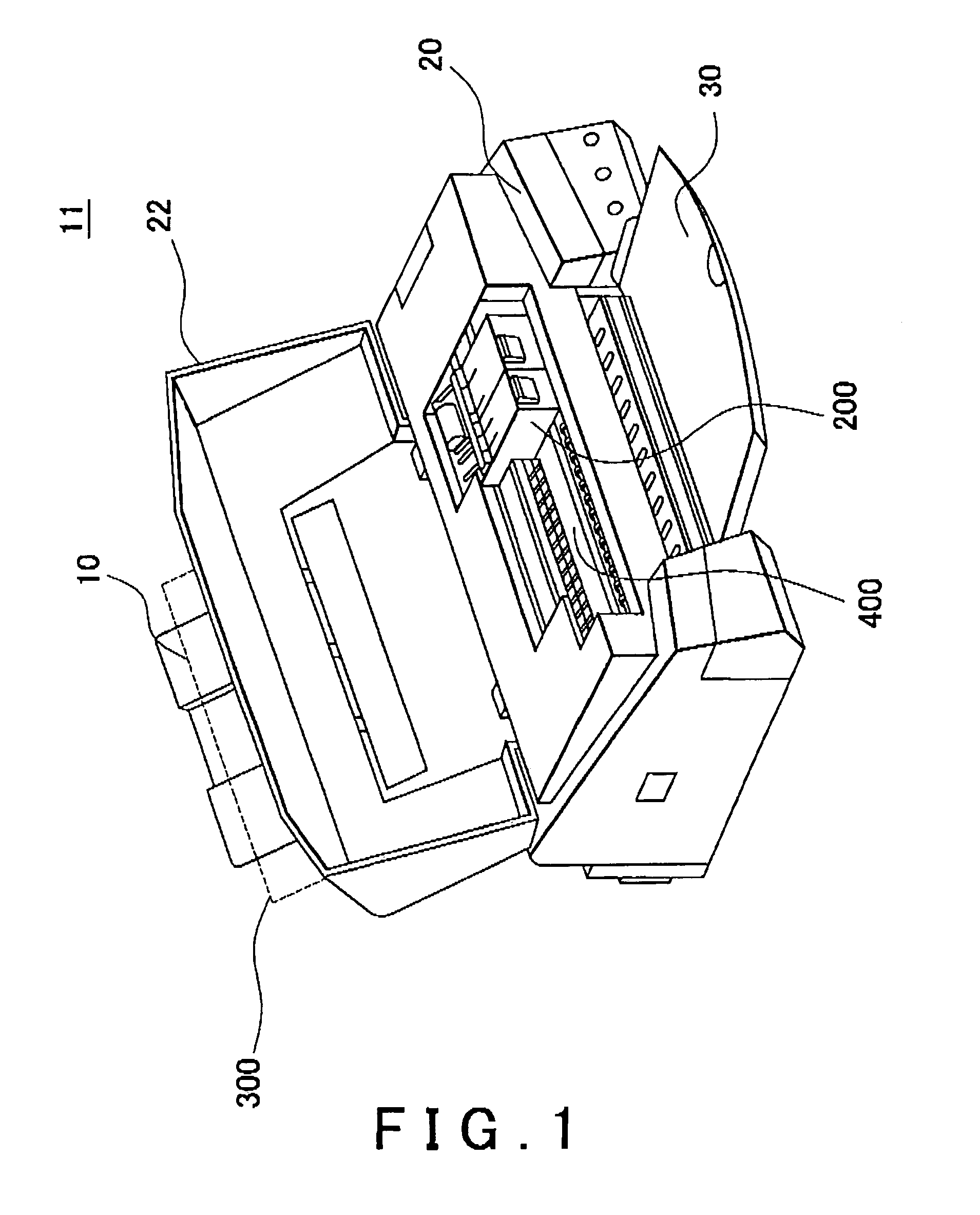
[0041]FIG. 1 is a perspective view showing the whole of an inkjet recording apparatus 11 which is one example of the liquid ejection apparatus. As shown in FIG. 1, The inkjet recording apparatus 11 includes a lower case 20 serving as a main component of the apparatus, a upper case 22 forming a housing in cooperate with the lower case 20, a paper support 10 attached to the backside of the lower case, 20 and a discharge tray 30 formed in front of the lower case 20. Here, as shown in FIG. 1, when the upper case 22 serving as a cover opens, a platen 400 horizontally disposed in the lower case 20 and a carriage 200 disposed above the platen 400 appear.

[0042]In the above-described inkjet rec...


PUM


Abstract

A liquid ejection apparatus includes: a recording head 210 having a nozzle plate including openings, for ejecting liquid to a recording article 300; an absorbing member 420 disposed further than the recording medium 300 on the orbit of the liquid ejected from the nozzle plate 260, for absorbing the liquid which has not applied on the recording medium 300; an waste liquid absorbing member 600 having capillarity higher than that of the absorbing member 420 and being in contact with the absorbing member 420 on the connecting surface which is different from the absorbing surface, for sucking on the liquid which has been absorbed in the absorbing member 420; and a potential difference generating means 700 for generating a potential difference between the absorbing surface and the connecting surface of the absorbing member 420 and attracting the solute of the liquid from the absorbing surface to the connecting surface through electrophoresis. Thereby a nonvolatile solute is prevented from accumulating around the surface of the absorbing member.

Description

CROSS REFERENCE TO RELATED APPLICATION[0001]The present application claims priority from Japanese Patent Applications Nos. JP 2005-044239 filed on Feb. 21, 2005, JP 2005-046269 filed on Feb. 22, 2005, JP 2006-009143 filed on Jan. 17, 2006 and JP 2006-009144 filed on Jan. 17, 2006, the contents of which are incorporated herein by reference.BACKGROUND OF THE INVENTION[0002]1. Field of the Invention[0003]The present invention relates to a liquid ejection apparatus and, more specifically, to a liquid ejection apparatus for applying the liquid which ejects from nozzle openings of a nozzle plate mounted on a liquid ejection head.[0004]2. Related Art[0005]Conventionally, when a liquid is applied all over the margin of a recording medium such as papers, the liquid is ejected over the region larger than the size of the recording medium because the recording medium and the liquid ejection head may be displaced. Therefore, the liquid is also ejected to the region around both side edges and the...

Claims


Application Information

Patent Timeline
Patent Type & Authority Patents(United States)
IPC IPC(8): B41J2/165
CPCB41J2/16523B41J11/0065B41J2002/1742
Inventor ENDO, TSUNENOBU
Owner SEIKO EPSON CORP
Why Eureka
Try Eureka