
Stencil assembly for marking pavement grade levels

a technology of stencils and grade levels, applied in the direction of manufacturing tools, instruments, roads, etc., can solve the problems of method or device used for making markings, and the need to employ more than one worker for marking, etc., to achieve the effect of simple us

Inactive Publication Date: 2009-01-06
VECCHIO CHARLES J
View PDF19 Cites 8 Cited by
  • Summary
  • Abstract
  • Description
  • Claims
  • Application Information

AI Technical Summary

Benefits of technology

[0004]An object of the invention is to provide a marking stencil that is of simplified yet most effective construction while at the same time simple to use.
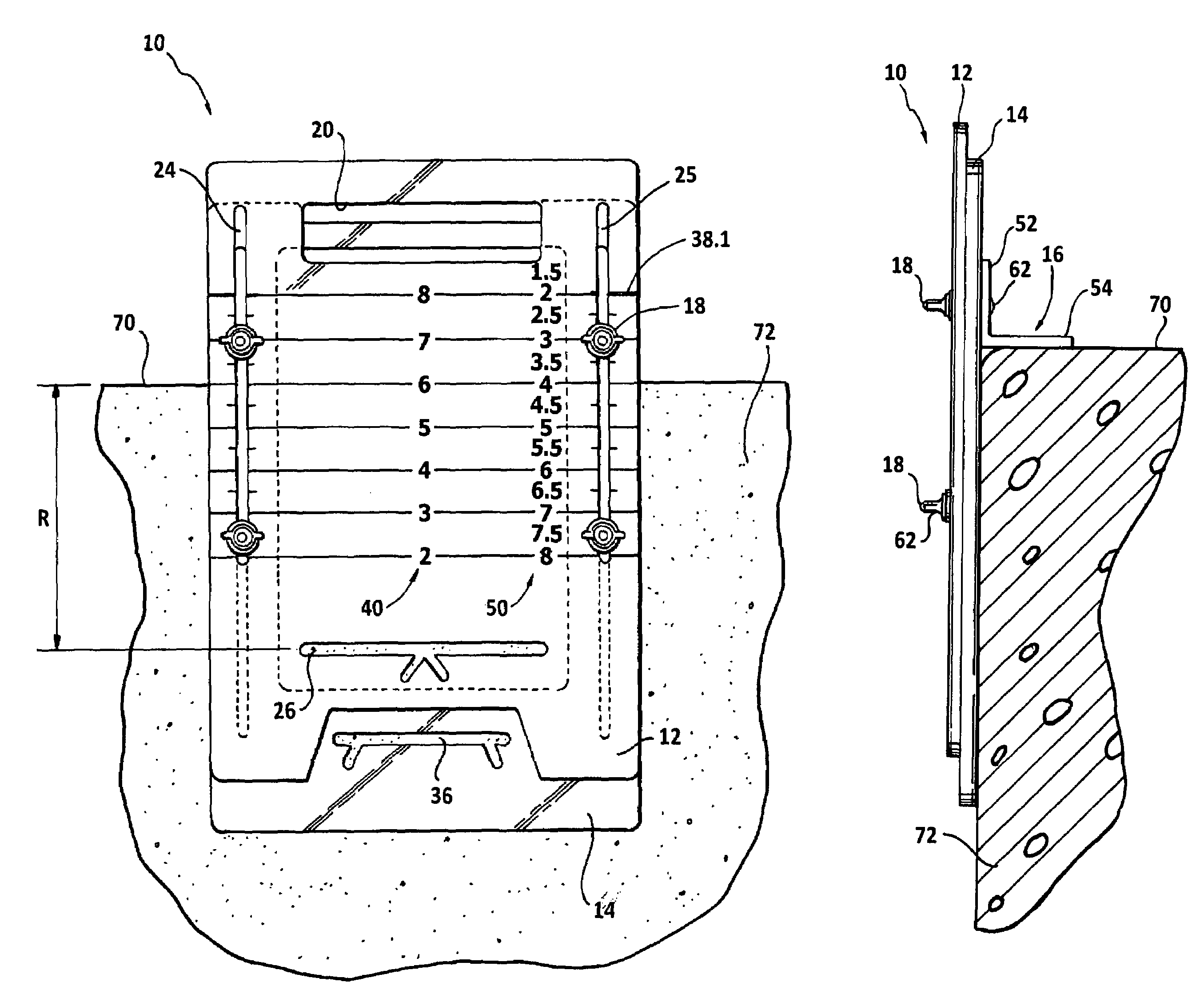
[0005]Another object is to provide a marking stencil that provides for reduction of the time it takes to effect site marking as compared to time involved when using prior art devices.
[0008]A still further object is to provide a marking stencil which is inexpensively fabricated.
[0009]Another object is to provide a marking stencil that has a long service life.
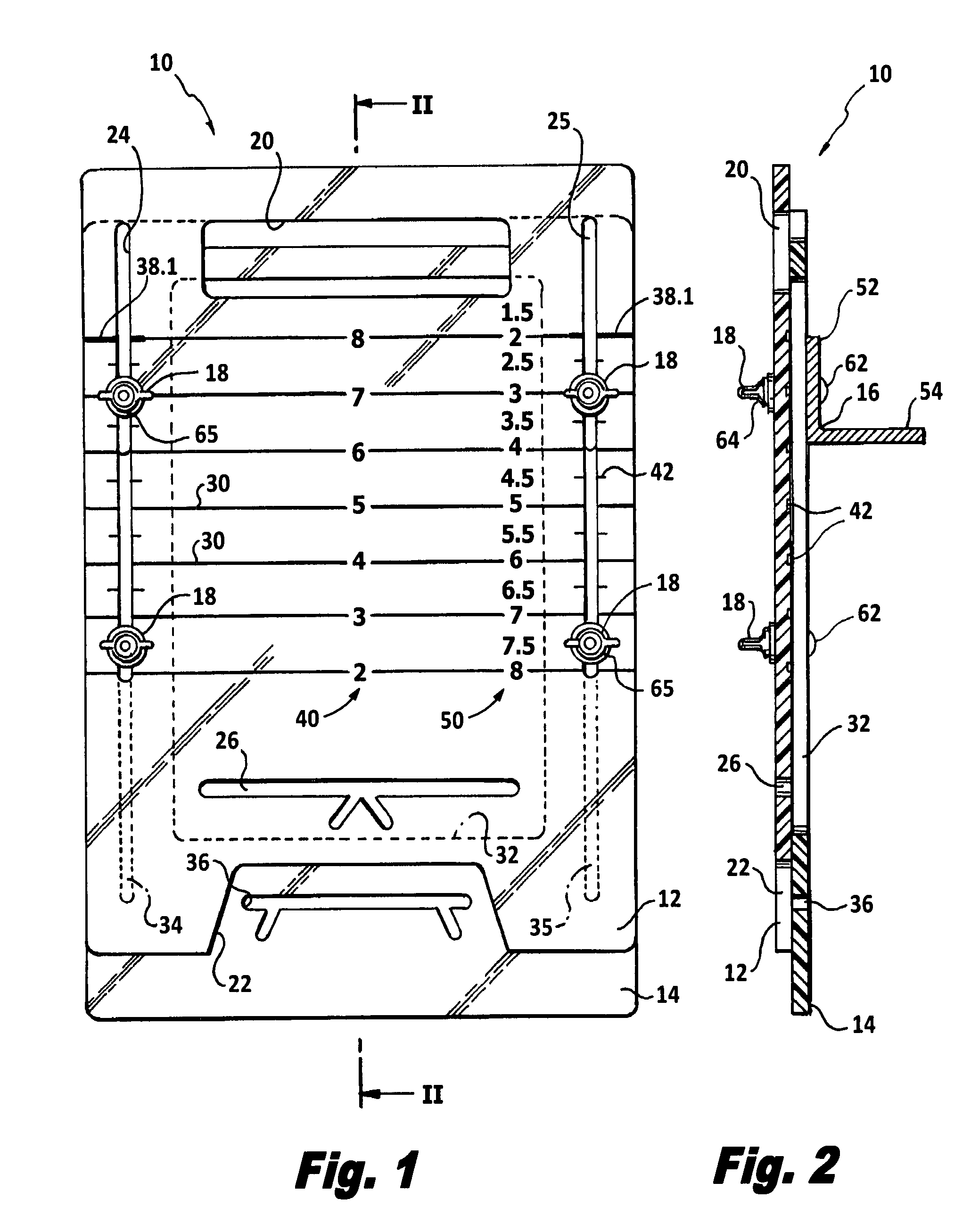
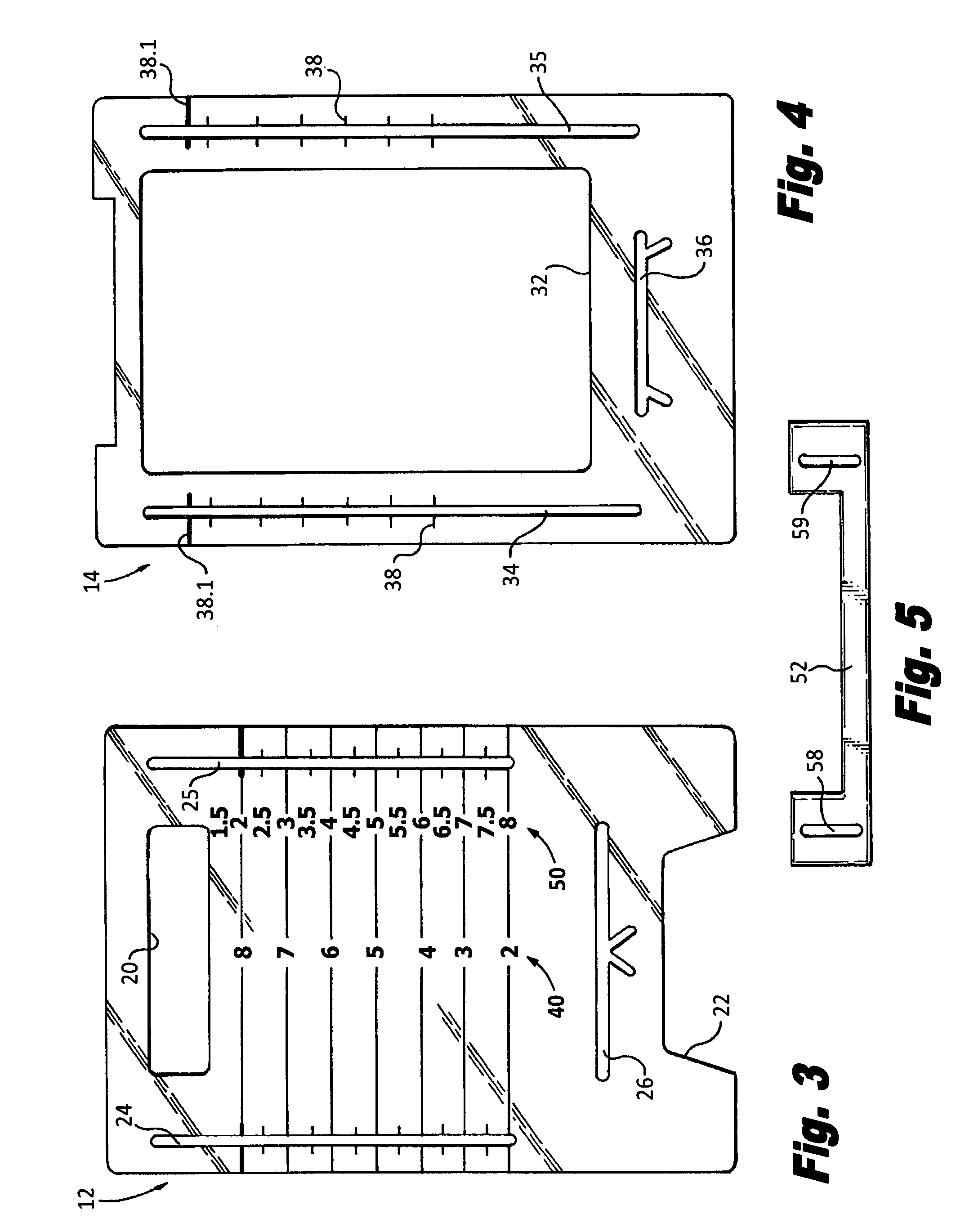
[0012]The arrangement of a captive fastening means allows for adjustably relatively positioning the front plate with respect to the back plate and for selectively positioning the support member on the back plate. A finish grade level indicia is carried on a lower part of the front plate, and a sub par grade indicia is carried on a lower part of the back plate. The front plate carries vertically uniformly spaced numeric indicator lines, numeric values associated with these lines increasing from a lowest value at the topmost line to a highest value at the lowermost line, these numerics being arranged in a vertical column proximal a margin of the front plate and being associated with a finish grade layer thickness. The back plate also carries graduation indicator lines arrayed at each of the two marginal side areas of the back plate. A selected one indicator line in at least one back plate indicator line array is highlighted to provide it with readily discernible appearance differentiating it from others of the indicators lines in the array. This selected one indicator line is the uppermost indicator line in the array and is a locator at which an indicator line on the front plate and associated with a selected finish grade layer thickness is positioned when setting the stencil for marking the selected finish grade level.
[0014]With the front and rear plate and the support member locked together, the stencil can then be placed on a top face of a curb, the plates depending down alongside an outside face of the curb. With the stencil thus located, the finish grade indicia on the front plate, and the sub par grade indicia on the back plate are vertically spaced, for example, 2 inches—this representing a selected one of thickness of the finish layer to be laid down. The finish grade and sub par grade indicia are formed in the associated plate as through openings in the respective plates. The openings can be fashioned as distinctive shapes, one clearly different in look than the other. The workman now applies a marking such as a paint spray through each indicia opening. The workman now lifts the stencil and moves along the paving line to a succeeding location where the marking procedure is repeated until the full paving course is marked. The paving operation can proceed along with and behind the marking operation since the marking operation is effectively and efficiently carried out without any lag or delay.

Problems solved by technology

A disadvantage of many prior art methods or devices used for making markings is the need to employ more than one worker for marking.
Where known marking practices can be employed with but one worker, the marking task is more time consuming than need be.

Method used


Image

  • Stencil assembly for marking pavement grade levels
  • Stencil assembly for marking pavement grade levels
  • Stencil assembly for marking pavement grade levels

Examples


Embodiment Construction

[0025]Referring to FIGS. 1 and 2, the stencil assembly 10 includes as assembled together components, a front plate 12, a back plate 14, and a support member 16. Plates 12 and 14 preferably are made from a transparent material such as a LEXAN type material. The plates 12, 14 and support member 16 are affixed or connected together with means such as upper and lower sets of fasteners 18.

[0026]Referring to FIG. 3, the front plate 12 is a flat member measuring approximately 15 inches length by approximately 10 inches width. An elongated opening 20 in a top area of the front plate is provided so as to define a stencil hand hold handle part to facilitate carrying and using the stencil. A recessed window slot 22 is provided in a bottom area of plate 12 for purpose as will be described later. Plate 12 is provided with elongated blind end slots 24, 25 disposed proximal each longitudinal margin of the plate. A finish grade level indicia 26 is formed in plate 12 being located a short distance a...


PUM


Abstract

A stencil assembly for marking paving required grade levels in a paving operation includes a front plate, a back plate and a support member, the support member being used to support the front and back plates on top of a curb. The front plate and the back respectively, carry finish grade level indicia, and sub par grade level indicia. The front and back plates can be relatively positioned one with respect to the other to present positioning of indicia at the levels where finish grade and sub par grade are to be located. The levels are marked on a side face of the curb so that sub par layer of, e.g., crushed stone can be applied up to the sub par grade level marking followed by applying the finish layer of, e.g., bituminous paving material up to the finish grade level, curb reveal at the outside face of the curb being a remaining distance between the finish grade level and the top of the curb.

Description

BACKGROUND OF THE INVENTION[0001]The present invention relates to a stencil assembly for marking grade levels at work sites where roadway, runway, parking area and analogous surface paving operations are being carried out. It is also applicable for effecting markings in walkway, driveway and tennis court paving jobs.[0002]In paving operations, various manners of indicating with markings, finish grade levels of paving material; such as asphalt or other material, as well as a level of a sub grade material such as crushed stone are known. Devices for use in defining or marking levels so as to guide work crews putting down layers of the materials also are known. A disadvantage of many prior art methods or devices used for making markings is the need to employ more than one worker for marking. These methods can involve use of marking rods and stakes and erection of string lines or other guide courses. Where known marking practices can be employed with but one worker, the marking task is ...

Claims


Application Information

Patent Timeline
IPC IPC(8): G01C5/00B28B19/00
CPCE01C19/00
Inventor VECCHIO, CHARLES J.
Owner VECCHIO CHARLES J
Learn More