Screen device

a screen device and screen technology, applied in the direction of curtain suspension devices, shutters/movable grilles, insect protection, etc., can solve the problems of increased time and effort for maintaining the slide-guide frame section, increased manufacturing cost, and inability to achieve quiet and stable open-close operation of the screen device, etc., to achieve convenient assembly, low price, and simple structure

Inactive Publication Date: 2009-01-06
SEIKI HANBAI CO LTD
View PDF9 Cites 22 Cited by
  • Summary
  • Abstract
  • Description
  • Claims
  • Application Information

AI Technical Summary

Benefits of technology

[0010]A technical subject of the present invention is to provide a screen device including a screen guide that has a simple structure, stably operates, and, in a guided-out state, is formed in a straight rail-like shape.
[0011]Also, another technical subject of the present invention is to provide a screen device including a screen guide which, in a simple form, can be prevented from curving in the horizontal lateral direction and bending in a reverse direction (raising from an installation surface) and always stably guide the end of the screen.
[0013]In the screen device according to the present invention, grooves allowing the wire members to be fitted therein and out are provided along the passage holes of the standing walls, thereby achieving easy attachment and detachment of each guide piece for its assembly, replacement, and the like, and also, intermediate rotors are interposed between the passage holes of the adjacent guide pieces, allowing the wire members to pass therethrough, thereby achieving smooth crooking between the guide pieces.
[0019]With the screen device according to the present invention, the screen guide has a simple structure in which the passage holes are formed along the tops of the standing walls of the guide piece constituting the screen guide and the two strings of the wire members are inserted through the passage holes, thereby not only offering a screen guide at low price but also achieving its easy assembly as well as improving its maintainability. In addition, the screen guide has a crooking portion provided at the upper parts of the standing walls of the guide piece (on the inner side of a crooked shape), thereby preventing parts of adjacent guide pieces from overlapping with each other. Also, the passage holes are formed in two strings of groove-like shapes when the screen guide extends in a straight pattern, thereby achieving a stable guide for an open-close operation of the screen.
[0020]Besides, when guided along the end of the screen, the screen guide is configured such that all or parts of serial contact surfaces of the adjacent guide pieces abut against each other, thereby preventing the screen guide from curving in the horizontal lateral direction of the screen and crooking in the reverse direction (raising from an installation surface). In addition, since the guide piece can be formed in a square or rectangular shape in side view, in a state of being guided-out, the screen guide can be formed in a straight rail shape having no undulations on its upper edge, resulting in not only a neat external appearance but also no problem of being caught with other objects (a screen and the like), thereby achieving a more stable open-close operation of the screen.

Problems solved by technology

Unfortunately, the screen device set forth in the foregoing Patent document 1 has disadvantages that, since the rigid unit constituting the slide-guide frame-section serving as a screen guide has a complicated structure, resulting in increase in not only its manufacturing cost but also time and effort for connecting the rigid units one another.
Also, the complicated structure causes increase in time and effort for maintaining the slide-guide frame section.
In addition, since the rigid units are rotatably connected one another, these units generate noises upon coming into contact with a floor surface and a frame member, hence, the screen device has no hope of achieving a quiet and stable open-close operation of the screen.

Method used


Image

  • Screen device
  • Screen device
  • Screen device

Examples


first embodiment

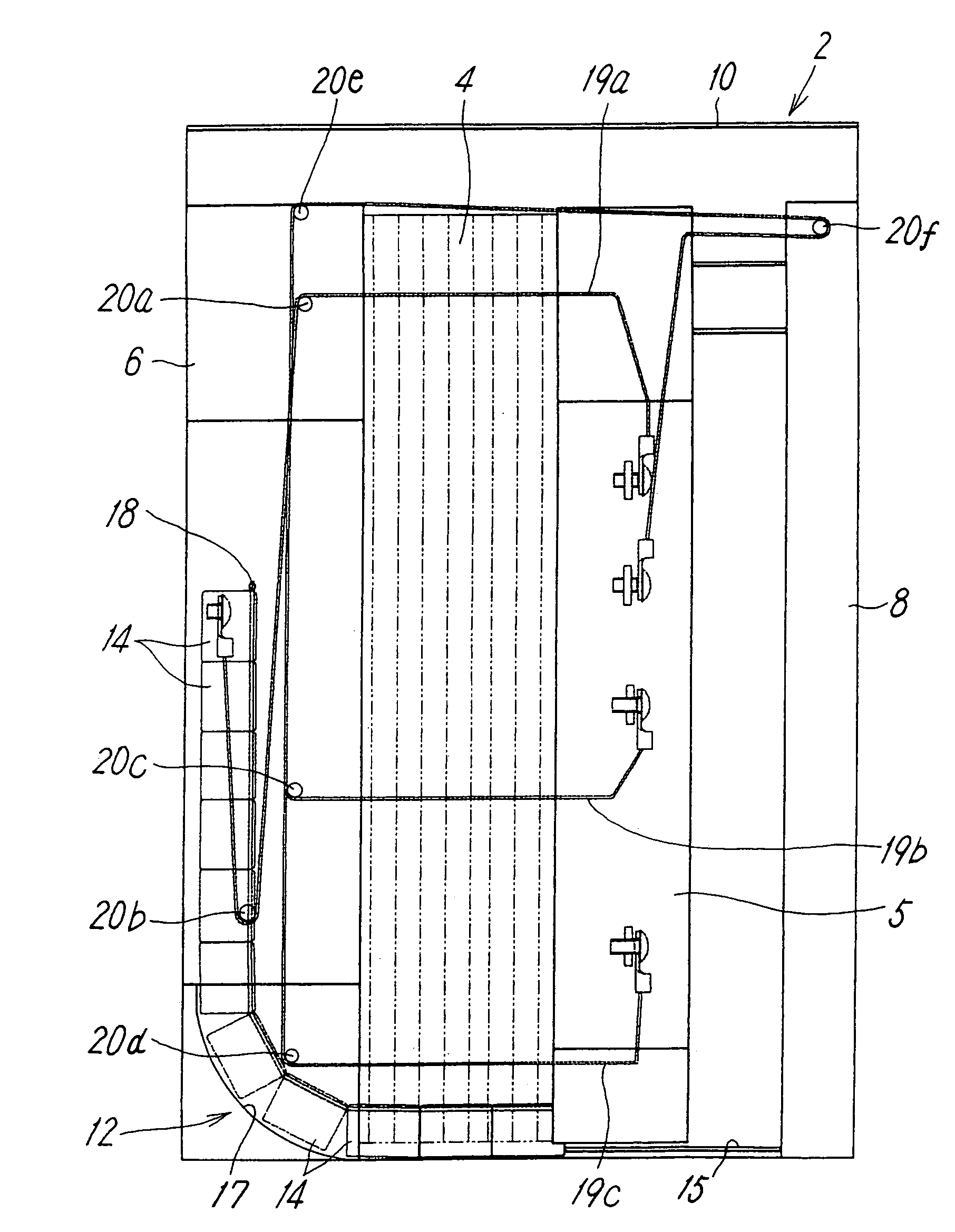
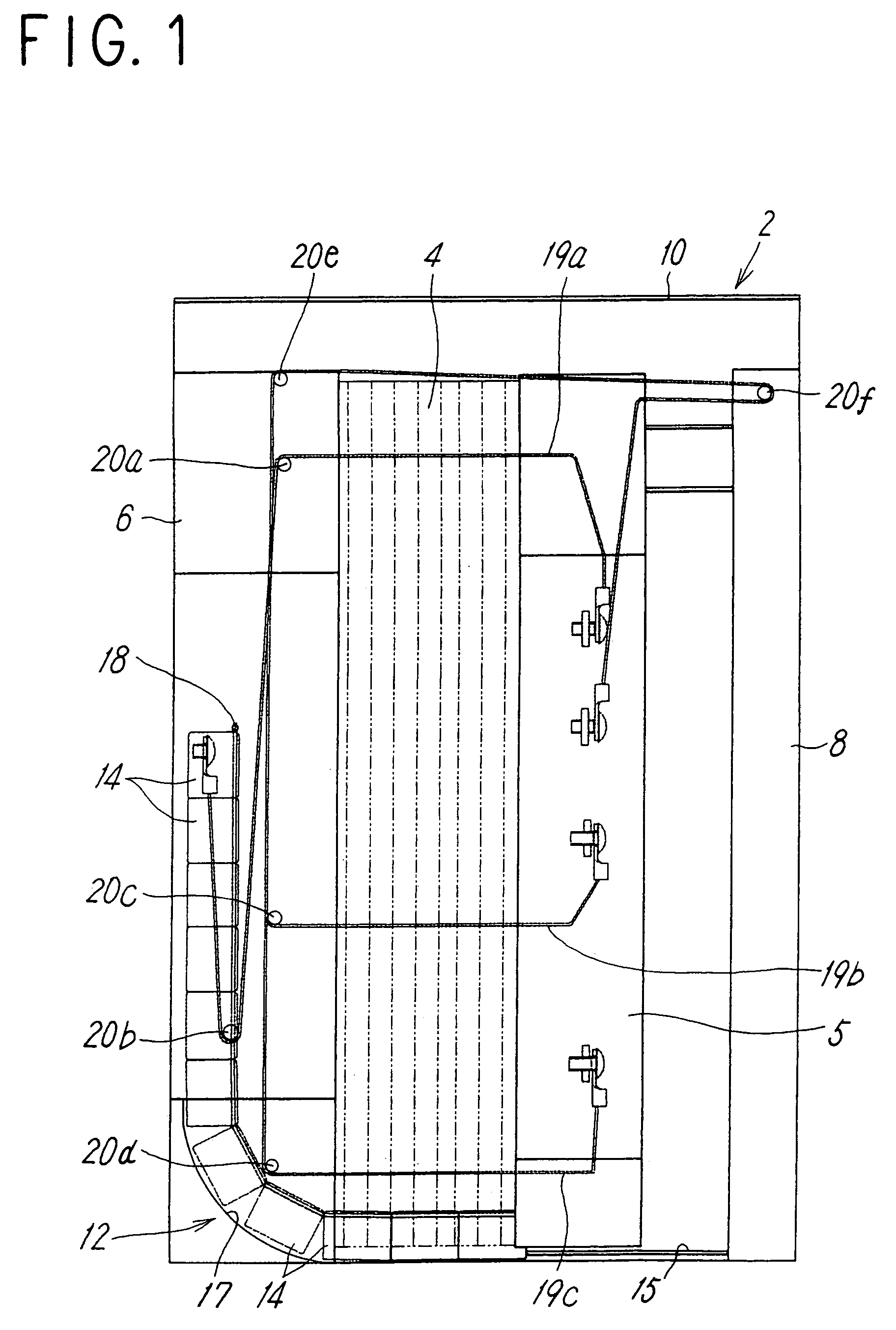
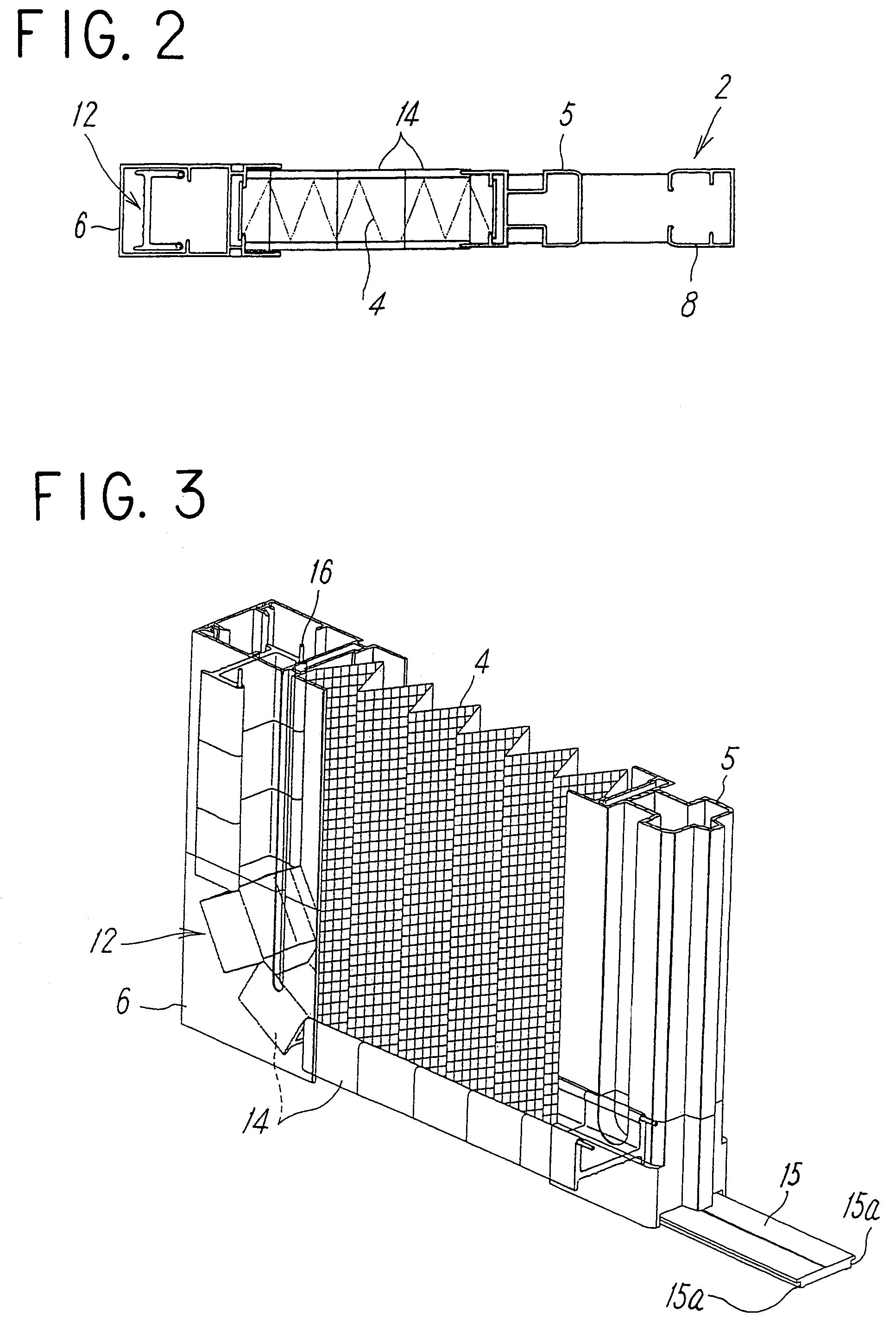
[0062]FIGS. 1 to 3 illustrate a screen device according to the present invention, configured to serve as an accordion-shape horizontal-drawing screen door to be installed at an opening of a building.

[0063]The horizontal-drawing screen door general includes a screen-door frame 2, a fly net 4 serving as a screen, openably fixed within the screen-door frame 2 by horizontal drawing, and a movable edge member 5 fixed to one end of the net 4, used for an open-close operation. The screen-door frame 2 includes right and left vertical frame members 6 and 8 and an upper horizontal frame member 10, and has a net guide (screen guide) 12 disposed at the lower part thereof and configured to guide the lower end of the net 4, so as to come in and out the vertical frame member 6 in accordance with movement of the movable edge member 5.

[0064]In the meantime, in FIGS. 1 and 3, for the sake of clarification of the drawings, the internal structures of the movable edge member 5 and the vertical frame mem...

second embodiment

[0087]FIGS. 12 and 13 illustrate a horizontal-drawing screen door having a structure in which one end of the net guide 12 is fixed to the lower end of the vertical frame member 6 having the one end of the net 4 fixed thereto, and the net guide 12 moves in and out the inside of the movable edge member 5 from its lower end in accordance with movement of the movable edge member 5. The net guide 12 itself can employ any one of the foregoing structures.

[0088]In the horizontal-drawing screen door according to the second embodiment, a parallel translation mechanism similar to the parallel translation mechanism of the first embodiment, employing three tension strings 191a to 191c is provided.

[0089]The first tension string 191a has its one end fixed to the upper part of the vertical frame member 6 having the net 4 fixed thereto, extends through the net 4 so as to be guided to the inside of the movable edge member 5, then, is guided downwards in the movable edge member 5 by a turning piece 2...

third embodiment

[0092]A horizontal-drawing screen door shown in FIG. 14, has a structure in which the net guide 12 moves in and out the insides of the vertical frame member 6 and the movable edge member 5 fixed to both ends of the net 4 from the respective lower ends and has tension strings, which will be described later, connected to both ends thereof without being fixed to any of the vertical frame member 6 and the movable edge member 5. Such an embodiment allows the net guide 12 to have a longer total length, thereby achieving a longer open-close length of the net 4.

[0093]Also, in this horizontal-drawing screen door, stretching four tension strings 192a to 192d, for example, between the screen-door frame 2 and the movable edge member 5 configures a parallel translation mechanism of the movable edge member.

[0094]The first tension string 192a has its one end fixed to the guide piece 14 located at the front of the side of the net guide 12, configured to move in and out the inside of the vertical f...


PUM


Abstract

A screen device including a screen guide that has a simple structure, stably operates, and, in a guided-out state, can be formed in a straight rail-like shape. A screen guide of the screen device includes a large number of guide pieces, each formed in an approximately U-shape by a bottom and standing walls respectively extending along the end of a screen and the external side surfaces of the screen, and having a structure in which passage holes are formed along the tops of the standing walls, two strings of wire members are exerted through the respective passage holes, and, when the screen guide is guided out along the end of the screen, the serial contact surfaces of the adjacent guide pieces abut against each other.

Description

TECHNICAL FIELD[0001]The present invention relates to a screen device including a screen guide configured to guide the end of a screen, extending along its open-close direction, and more particularly, with respect to a screen, e.g., a fitting such as a screen door, a partition, or a curtain, it relates to a screen device including a screen guide configured to, in response to an open-close operation of the screen, crookedly move in and out the inside of at least one of frame members fixed to both ends of the screen in its open-close direction, and be guided out along the end of the screen lying in a tension state so as to guide the end.BACKGROUND ART[0002]A screen device including a screen guide configured to guide the end of a screen has a structure in which, in response to an open-close operation of the screen, the screen guide crookedly moves in and out the inside of at least one of frame members fixed to both ends of the screen in its open-close direction and is guided out along ...

Claims


Application Information

Patent Timeline
Patent Type & Authority Patents(United States)
IPC IPC(8): A47H5/00A47G5/02A47H1/00E06B9/52
CPCE06B9/52E06B9/522E06B2009/543E06B9/06E06B3/94
Inventor KAMOSAWA, YOJITODA, HIROTSUGUCHINO, MITSUHIKOMORIYA, MASATO
Owner SEIKI HANBAI CO LTD
Why Eureka
Try Eureka