Cooking tool

a technology of cooking tool and cooking plate, which is applied in the field of cooking plate, can solve the problems of requiring a prolonged cooking time, unable to finish cooking as desired, and the actual temperature of the cooking plate b>103/b> cannot be detected at a high precision, so as to achieve high caloric force, reduce caloric force, and high precision

Inactive Publication Date: 2009-01-06
IRIS OHYAMA
View PDF16 Cites 191 Cited by
  • Summary
  • Abstract
  • Description
  • Claims
  • Application Information

AI Technical Summary

Benefits of technology

[0008](3) When the cooking tool 103 is continuously heated at a high caloric force, the actual temperature of the cooking tool 103 rises at the same rate as before boiling also after reaching boiling temperature. Therefore, when the percent change of detected temperature falls below criterion, water has already been boiled, causing some delay in the detection of boiling. Accordingly, the caloric force is stepwise lowered to reduce the percent change of temperature of the cooking tool 103 when water is boiled, preventing the occurrence of delay in the detection of boiling.
[0009]It is therefore an aim of the invention to provide a cooking tool for use in a heat cooking apparatus capable of finishing cook as desired in a short period of time.Means for Overcoming the Problem
[0015]The actual temperature of the cooking tool can be detected with a high precision without making any stepwise control for reducing the caloric force. Therefore, the cooking tool can be continuously heated with a high caloric force, making it possible to finish cook as desired in a short period of time. Further, since infrared rays to be used as transmitting media for temperature data can be transmitted over a wider range than electric wave and are not affected by magnetic field, temperature data can be transmitted to the receiving unit accurately and certainly without being affected by the installation position of the cooking tool.

Problems solved by technology

The aforementioned heat cooking device performs stepwise control of lowering calorific force and thus requires a prolonged cooking time.
Accordingly, when the stepwise control of lowering caloric force is suspended, the actual temperature of the cooking tool 103 cannot be detected at a high precision, making it impossible to finish cooking as desired.

Method used


Image

  • Cooking tool
  • Cooking tool
  • Cooking tool

Examples


embodiment 1

[0038]A first embodiment of implementation of the invention will be described in connection with FIGS. 1 and 10.

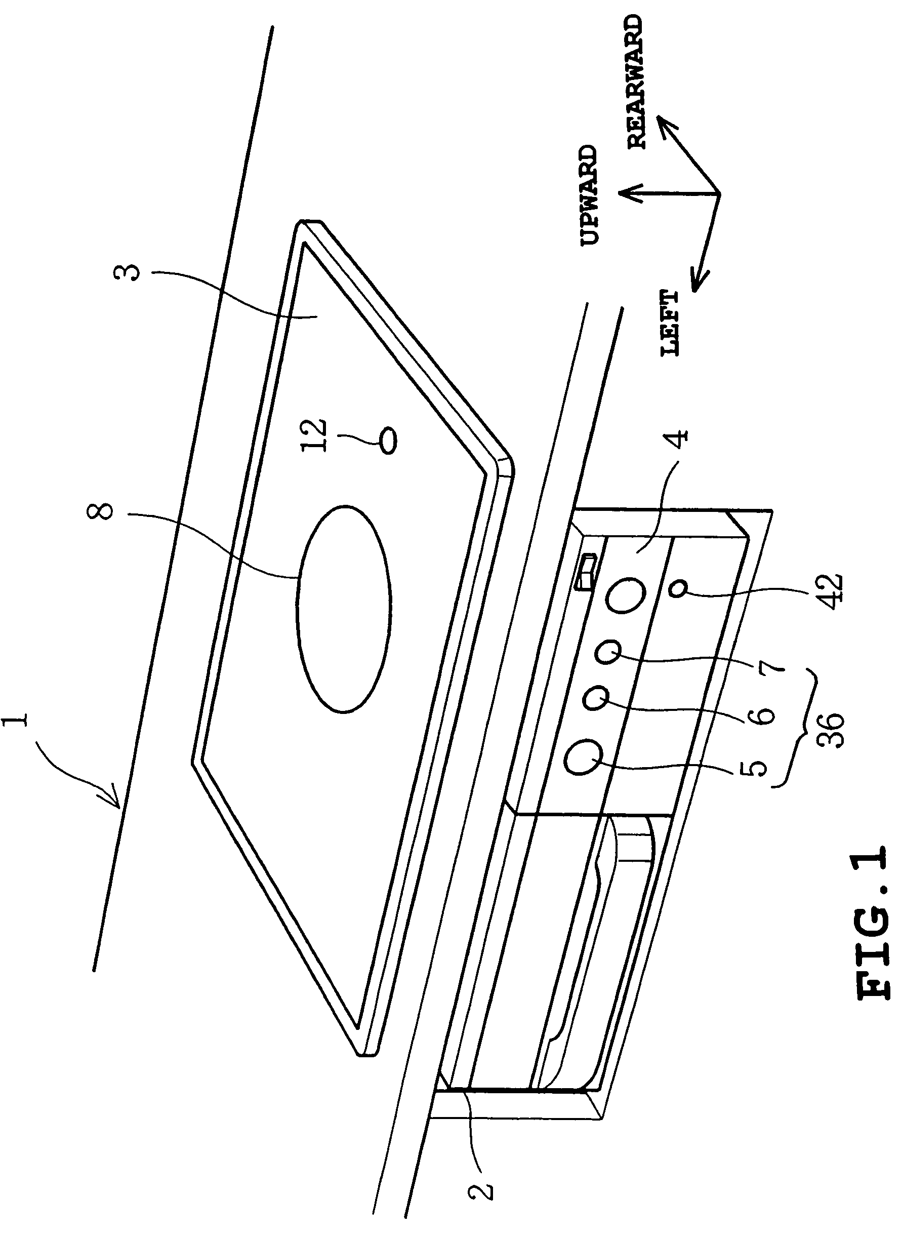
[0039]FIG. 1 is a perspective view illustrating the external appearance of a cooking heater. In the interior of a system kitchen 1 is received a cabinet 2. On the upper surface of the cabinet 2 is provided a top plate 3 made of heat-resistant glass corresponding to supporting unit. The top plate 3 is exposed at the upper surface of the system kitchen 1. The top plate 3 is colored to opacity so that the interior of the cabinet 2 cannot be seen through the top plate 3.

[0040]In front of the cabinet 2 is provided a control panel 4 provided with an automatic water boiling key 5, a caloric force adjusting dial 6 and a tempura (Japanese deep-fat fried food) key 7. These keys correspond to units of inputting cooking conditions. In this arrangement, control can be made on the front.

[0041]On the top plate 3 is formed a circular heating mark 8. The heating mark 8 is colored to a colo...

embodiment 2

[0105]A second embodiment of implementation of the invention will be described in connection with FIGS. 11 and 13.

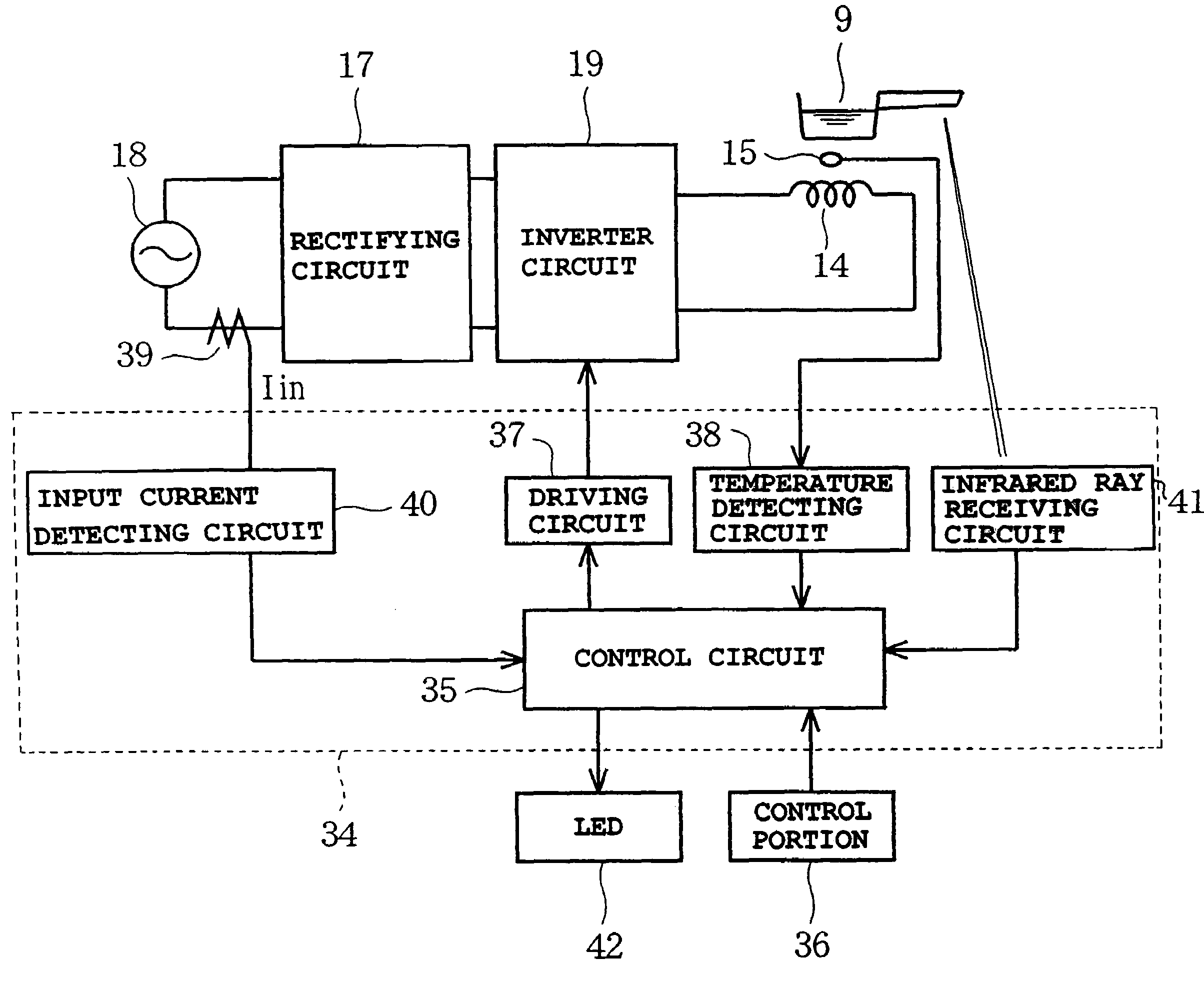
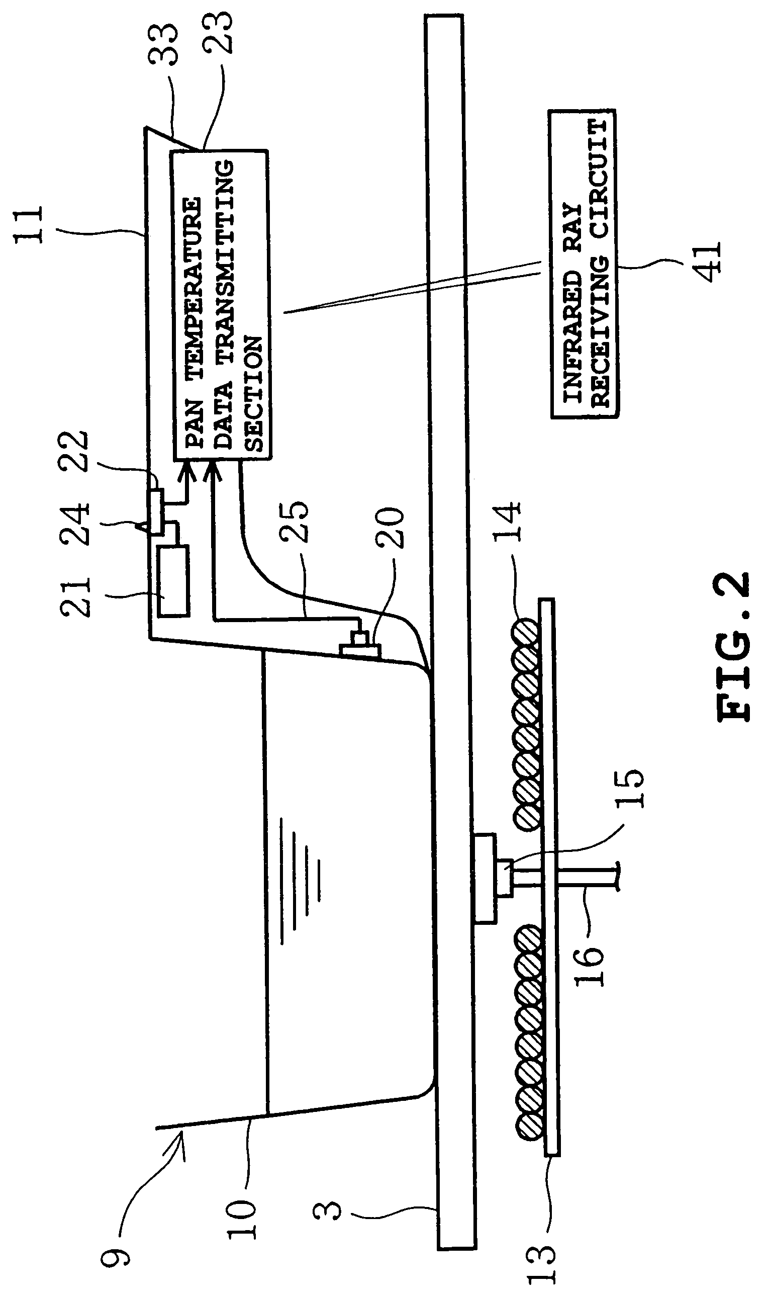
[0106]FIG. 11 depicts a dedicated cooking tool 9 set on a top plate 3. FIG. 12 depicts the electrical configuration of a temperature data transmitting portion 23 and its peripheral circuits.

[0107]The handgrip 11 of the dedicated cooking tool 9 has a temperature switch 43 provided in a handgrip cover 33 as a switching unit. The pan electric supply 21 is connected to an electric supply circuit 26 via the temperature switch 43. The temperature switch 43 has a bimetal as a moving contact. The temperature switch 43 switches ON or OFF across the detected temperature Tb as a border. In some detail, when the surface temperature To of the cooking tool 9 is not greater than the detected temperature Tb, the temperature switch 43 switches OFF to deenergize the temperature data transmitting portion 23. On the contrary, when the surface temperature To of the cooking tool 9 exceeds the...

embodiment 3

[0110]A third embodiment of implementation of the invention will be described in connection with FIGS. 14 to 16.

[0111]FIG. 14 depicts a dedicated cooking tool 9 set on a top plate 3. FIG. 15 depicts the electrical configuration of the temperature data transmitting portion 23 and its peripheral circuits.

[0112]The dedicated cooking tool 9 has an annular loop coil 44 attached thereto on the lower surface of the container portion 10. The loop coil 44 is a secondary coil which is magnetically connected to IH coil 14 while the cooking tool 9 is set on the heating mark 8 of the top plate 3. The loop coil 44 is connected to the rectifying circuit 45 of the temperature data transmitting portion 23. The rectifying circuit 45 is adapted to rectify the induced voltage of the loop coil 44. The rectifying circuit 45 has a switching electric supply circuit 46 corresponding to stabilizing electric supply portion connected thereto. The switching electric supply circuit 46 is adapted to keep the outp...


PUM


Abstract

A heat cooking apparatus includes a supporting unit for supporting a cooking tool, a heating unit for heating the cooking tool, a receiving unit capable of receiving temperature data of the cooking tool transmitted in the form of infrared rays from the exterior, and a controlling unit for controlling the heating unit on the basis of temperature data received by the receiving unit.

Description

[0001]This is the U.S. National Stage of International Patent Application No. PCT / JP2004 / 012498, filed on Aug. 30, 2004, which, in turn, relies for priority upon Japanese Patent Application No. 2003-393808, filed Nov. 25, 2003, the contents of both of which are incorporated herein by reference in their entireties.TECHNICAL FIELD[0002]The present invention relates to a cooking tool for use with a heat cooking apparatus.BACKGROUND ART[0003]FIG. 19 depicts an example of the related art heat cooking device. A thermistor 102 is provided in the vicinity of the center of IH coil 101. This heat cooking device is arranged such that the surface temperature of a cooking tool 103 placed on a top plate 104 is indirectly detected by the thermistor 102. During automatic water boiling process, the heat cooking device lowers the caloric force stepwise from a high value to a low value via a middle value as the temperature detected by the thermistor 102 rises. When the percent change of detected tempe...

Claims


Application Information

Patent Timeline
Patent Type & Authority Patents(United States)
IPC IPC(8): H05B6/00H05B6/12H05B6/06
CPCH05B6/062H05B2213/06H05B2213/07A47J36/321H05B6/06H05B6/12
Inventor TAKIMOTO, HITOSHI
Owner IRIS OHYAMA
Why Eureka
Try Eureka