Test circuit and test method
a test circuit and test method technology, applied in the direction of electronic circuit testing, measurement devices, instruments, etc., can solve the problems of inability to implement testing, increasing the load on automatic test pattern generation, etc., to achieve efficient memory refresh, efficient memory refresh, and efficient memory refresh
- Summary
- Abstract
- Description
- Claims
- Application Information
AI Technical Summary
Benefits of technology
Problems solved by technology
Method used
Image
Examples
first embodiment
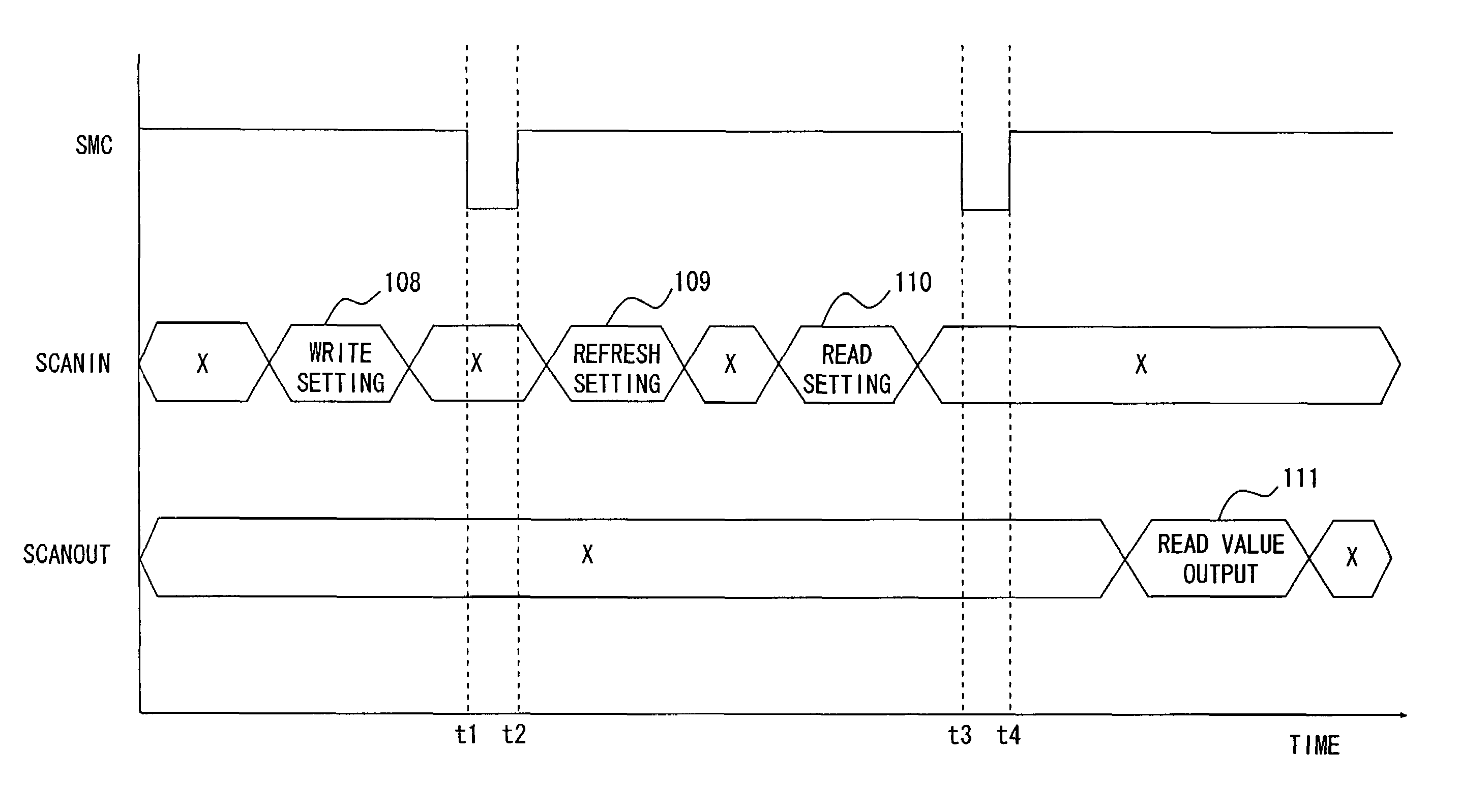
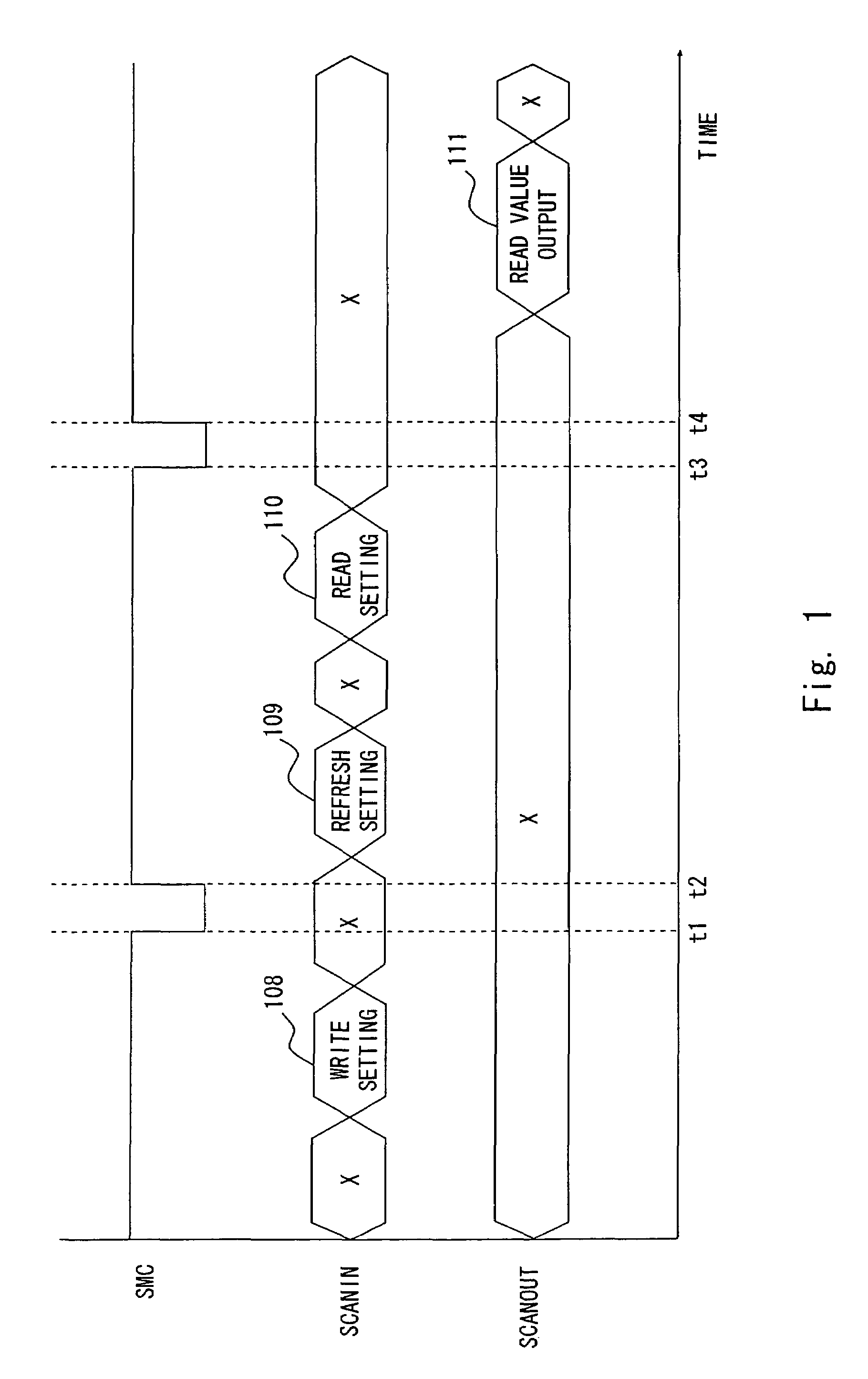
[0034]A test circuit according to an embodiment of the invention is described hereinafter with reference to FIG. 1. The test circuit according to this invention is adapted to a monolithic semiconductor device equipped with DRAM. In FIG. 1, “SMC” indicates a value of a signal SMC for selecting whether to set a scan path to shift operation or normal operation without shifting, “SCANIN” indicates a value of a scan input, and “SCANOUT” indicates a value of a scan output. In this embodiment, the value of SMC is such that “1” represents shift mode and “0” represents normal mode when no shift occurs. The state different from the shift mode is called capture mode.
[0035]Time t1 indicates when the mode changes from the shift mode to the capture mode. Time t2 indicates when the mode changes from the capture mode to the shift mode for the time firstly after t1. Time t3 indicates when the mode changes from the shift mode to the capture mode again after t2. Time t4 indicates when the mode changes...
second embodiment
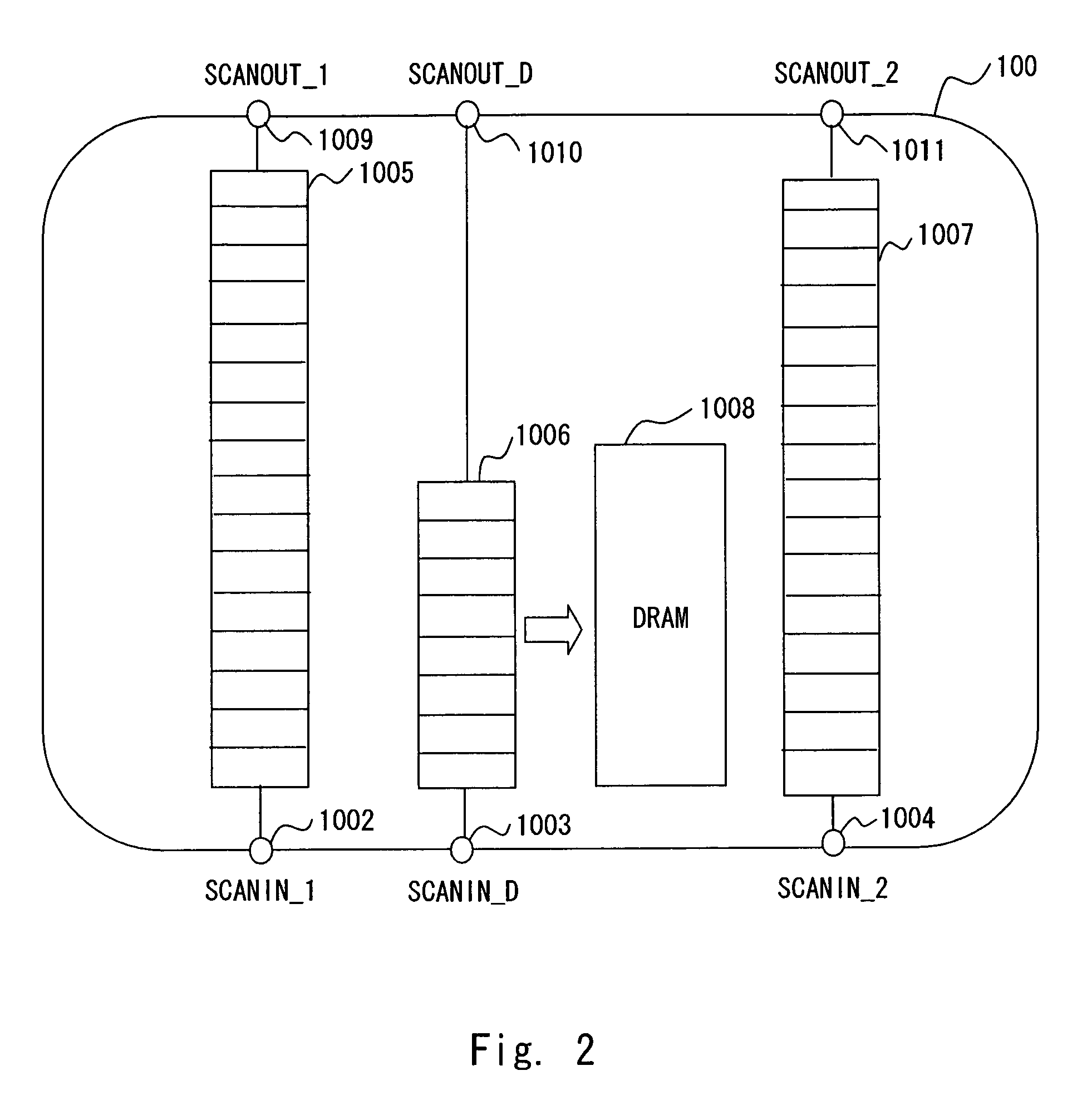
[0077]A second embodiment of the present invention is described hereinafter with reference to FIG. 2. The test circuit according to this invention is adapted to a monolithic semiconductor device equipped with DRAM. FIG. 2 shows the configuration of a test circuit according to the second embodiment of the invention. The test circuit 100 includes scan input terminals 1002, 1003 and 1004, flip-flop groups 1005, 1006 and 1007, DRAM 1008, and scan output terminals 1009, 1010 and 1011.
[0078]The test circuit 100 is composed of three scan paths. The flip-flops for setting the DRAM 1008 are included only in the scan path SCAN_D which receives a scan input through the scan input terminal 1003, outputs a scan output through the scan output terminal 1010, and has the flip-flop group 1006 to form the scan path.
[0079]The other scan paths are SCAN_1 which is composed of the scan input 1002, the flip-flop group 1005 and the scan output 1009 and SCAN_2 which is composed of the scan input 1004, the f...
PUM
 Abstract
Description
Claims
Application Information
 - R&D
- Intellectual Property
- Life Sciences
- Materials
- Tech Scout
- Unparalleled Data Quality
- Higher Quality Content
- 60% Fewer Hallucinations
Browse by: Latest US Patents, China's latest patents, Technical Efficacy Thesaurus, Application Domain, Technology Topic, Popular Technical Reports.
© 2025 PatSnap. All rights reserved.Legal|Privacy policy|Modern Slavery Act Transparency Statement|Sitemap|About US| Contact US: help@patsnap.com


