Electromagnetic pulse generator

a technology of electromagnetic pulses and generators, applied in the direction of electric devices, braking systems, anti-theft devices, etc., can solve the problems of motorized vehicles including mobile command and control centers, needing to be disabled in tactical situations, and inherent danger of having to deploy the system by hand

Inactive Publication Date: 2009-01-13
THE UNITED STATES OF AMERICA AS REPRESENTED BY THE SECRETARY OF THE NAVY
View PDF11 Cites 19 Cited by
  • Summary
  • Abstract
  • Description
  • Claims
  • Application Information

AI Technical Summary

Problems solved by technology

Situations arise when it is necessary to disable motorized vehicles.
These high-speed pursuits represent a potential hazard to life and property.
Similarly, motorized vehicles, including mobile command and control centers, need to be disabled in tactical situations, for example during a military engagement.
The disadvantages of the spike-strip system include the need to anticipate the target vehicle's path and the inherent danger associated with having to deploy the system by hand.
In addition, the spike-strip presents a danger to other vehicles traveling along the same path, including the pursuit vehicles.
This system, however, is limited to application on vehicles that can be accessed in advance for installation of the signal receiving unit and other necessary equipment.
This type of access is typically not available in spontaneous police pursuits and tactical engagements with hostile enemies.
In addition, there are significant costs associated with the equipment and its installation.
Since modem motorized equipment in general, and in particular automobiles, utilize electrical systems and computer electronics, disabling these systems disables the vehicle.
These systems, however, require bulky and expensive equipment to deliver the desired EMP.

Method used


Image

  • Electromagnetic pulse generator
  • Electromagnetic pulse generator
  • Electromagnetic pulse generator

Examples


Embodiment Construction

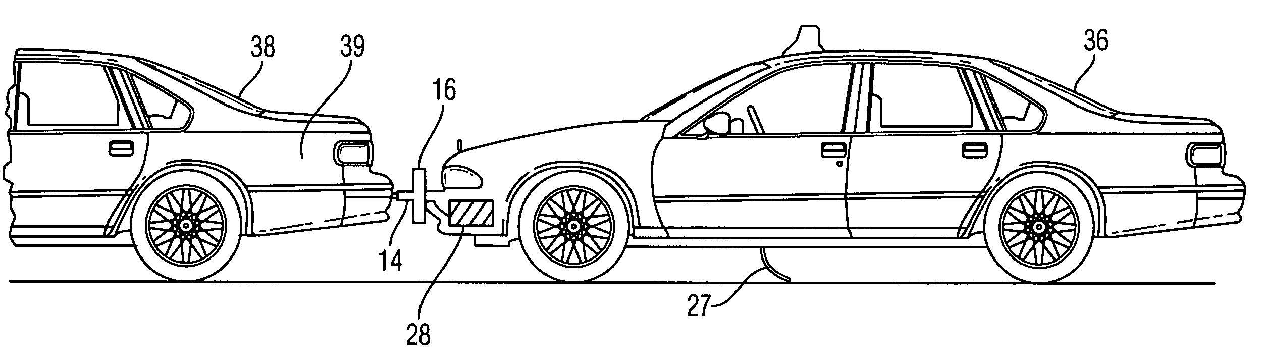
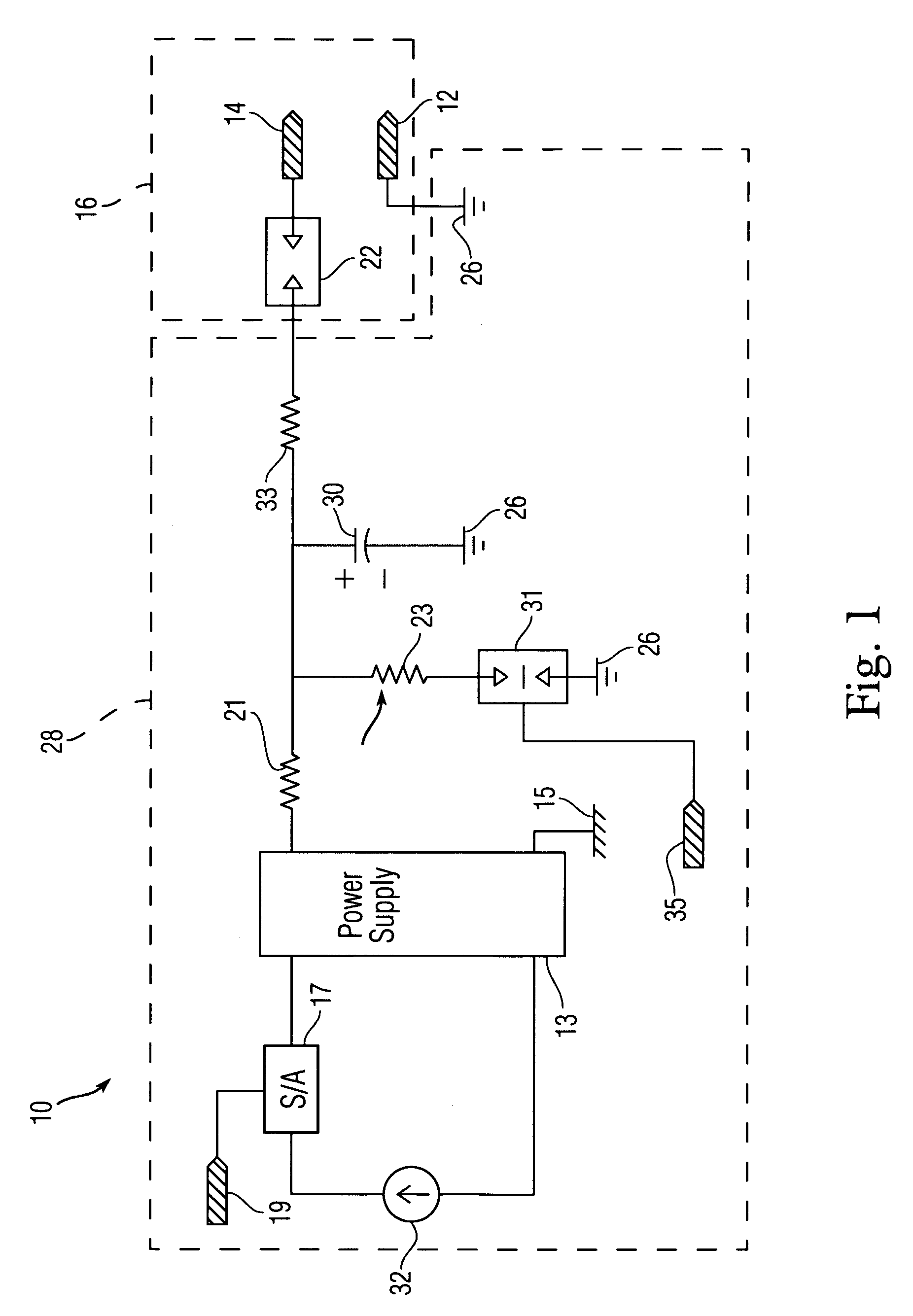
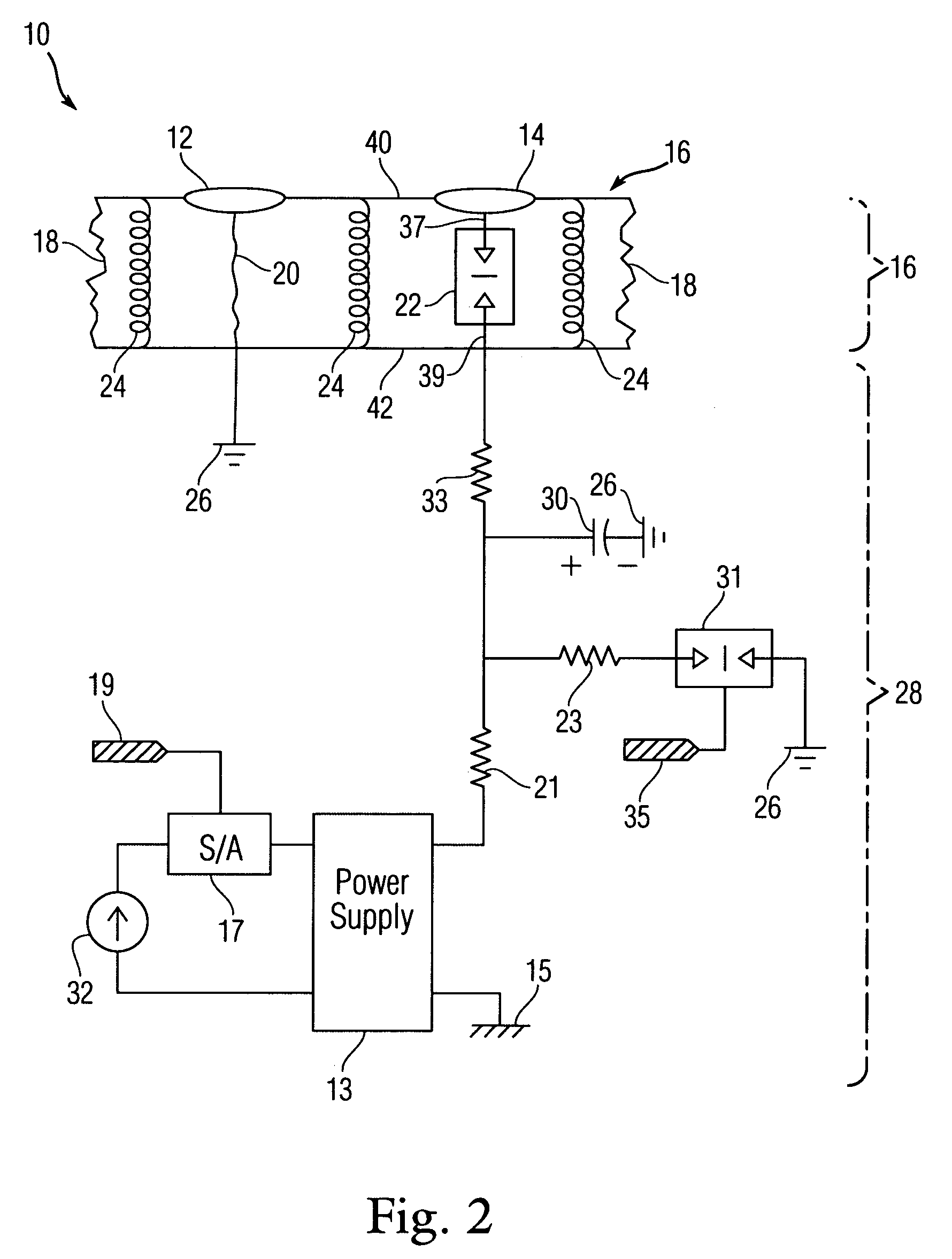
[0015]Referring initially to FIG. 1, an exemplary embodiment of an electromagnetic pulse (EMP) delivery system 10 in accordance with the present invention is illustrated. In an embodiment, the EMP delivery system 10 is mounted to a mobile delivery platform, for example, a motorized vehicle, such as an automobile. The EMP delivery system 10 includes a capacitive discharge system 28, which includes a power source 32 in communication with a high voltage power supply 13. The power source 32 supplies the necessary electrical power to the capacitive discharge system 28. Suitable power sources include batteries, such as automobile batteries, alternators and generators, such as automobile alternators, electrical power grids, alternating current from municipal power supplies and combinations thereof. In an alternate embodiment, the EMP delivery system 10 may be mounted on a stationary delivery platform.

[0016]The power derived from the power source 32 is fed into a high voltage power supply 1...


PUM


Abstract

An electromagnetic pulse delivery system for delivering a sufficient amount of energy and waveform to induce a current in target electronic components that disrupt or damage those target electronic components and overwhelm any protective circuitry. The system includes a power source in communication with a capacitive discharge system capable of producing an electromagnetic pulse. A mechanical interface including a supply contact in communication with the capacitive discharge system and a return contact in communication with a path to earth ground is provided to deliver the electromagnetic pulse to the target object. Physical contact between the mechanical interface and the object closes a switch disposed between the capacitive discharge system and the supply contact for discharging the pulse into the target object.

Description

STATEMENT OF GOVERNMENT INTERESTS[0001]The invention described herein may be manufactured and used for the Government of the United States of America for governmental purposes without payment of any royalties thereon or therefore.FIELD OF THE INVENTION[0002]The present invention is directed to systems for the generation and delivery of electromagnetic pulses.BACKGROUND OF THE INVENTION[0003]Situations arise when it is necessary to disable motorized vehicles. For example, law enforcement officers often have the need to disable or stop suspect vehicles in order to apprehend suspects and to avoid high-speed vehicular pursuits through residential neighborhoods and public streets. These high-speed pursuits represent a potential hazard to life and property. Similarly, motorized vehicles, including mobile command and control centers, need to be disabled in tactical situations, for example during a military engagement.[0004]Various systems have been used to disable motorized vehicles. The m...

Claims


Application Information

Patent Timeline
Patent Type & Authority Patents(United States)
IPC IPC(8): F41B15/04B60L1/00B60T7/16
CPCB60L1/00B60R25/04F41H13/0093Y02T90/16
Inventor DAILY, ROBERT M.
Owner THE UNITED STATES OF AMERICA AS REPRESENTED BY THE SECRETARY OF THE NAVY
Why Eureka
Try Eureka