High efficiency high energy firing rate CD ignition

a high energy firing rate, high efficiency technology, applied in the direction of machines/engines, induction energy storage installations, other installations, etc., can solve the problems of slow recharging of discharge capacitors to a potentially lower energy and peak voltage, inefficient current capacitive discharge ignition systems, and high efficiency

Inactive Publication Date: 2003-07-01
WARD MICHAEL A V
View PDF4 Cites 18 Cited by
  • Summary
  • Abstract
  • Description
  • Claims
  • Application Information

AI Technical Summary

Problems solved by technology

Current capacitive discharge (CD) ignition systems are very inefficient, with typically 15% to 25% efficiency, and deliver typically only 20 to 30 millijoules (mJ) of spark energy per single spark pulse (into an industry standard 800 volt Zener load).
This results in slower recharging of the discharge capacitors to a potentially lower energy and peak voltage, as well as poorer use of the power source.
This can be a particular problem when lower energy is available for delivery to the capacitor, as in the case of engines running at very high speeds (less charging time) or flying magnet systems under engine cranking conditions.
Such designs reduce the coil discharge efficiency and increase coil heat dissipation.
In the case of high speed engines with single coil distributor ignitions, high circuit efficiency along with use of the preferred triangular, versus sinusoidal, primary and secondary winding spark current distribution leads to problems at high engine speeds when a coil may be fired well above 200 Hertz (Hz).
This problem occurs because of the imperfect coupling between the primary and secondary windings (k<1), resulting in a residual primary current after the secondary current has dropped to zero.
While this problem may be largely off-set by designing the discharge circuit for the sinusoidal current distribution, this has several drawbacks, including and not limited to not allowing charging of the discharge capacitor during spark firing.
In the automotive case where battery power is used (12, 24, or future 42 volt), the power converters which are used to step-up the voltage to the typical 200 to 600 volts are generally inefficient and electrically noisy, with efficiencies between 35% and 70%, and up to 85% in practice in my U.S. Pat. No. 5,558,071.

Method used


Image

  • High efficiency high energy firing rate CD ignition
  • High efficiency high energy firing rate CD ignition
  • High efficiency high energy firing rate CD ignition

Examples


Embodiment Construction

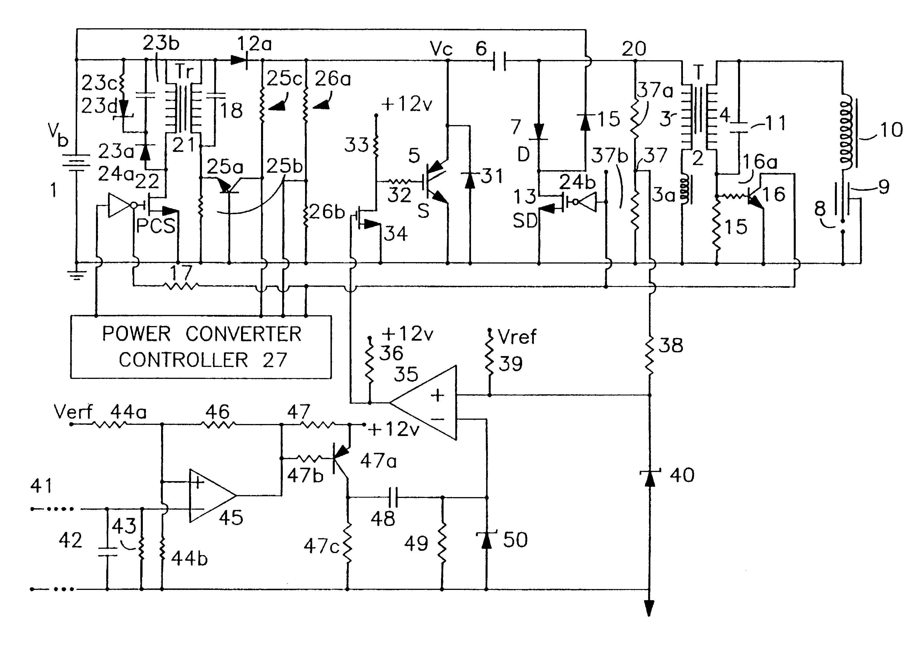
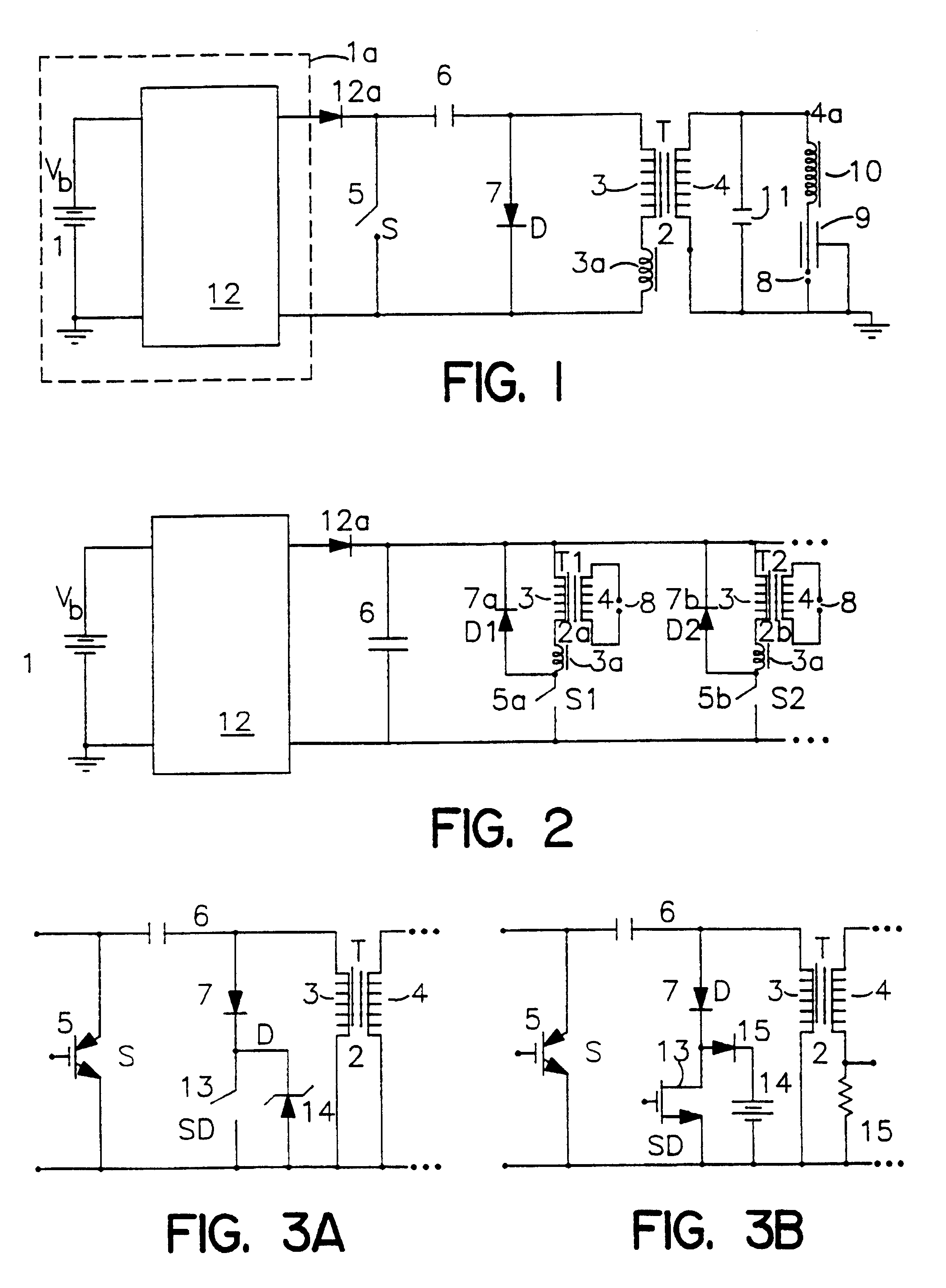
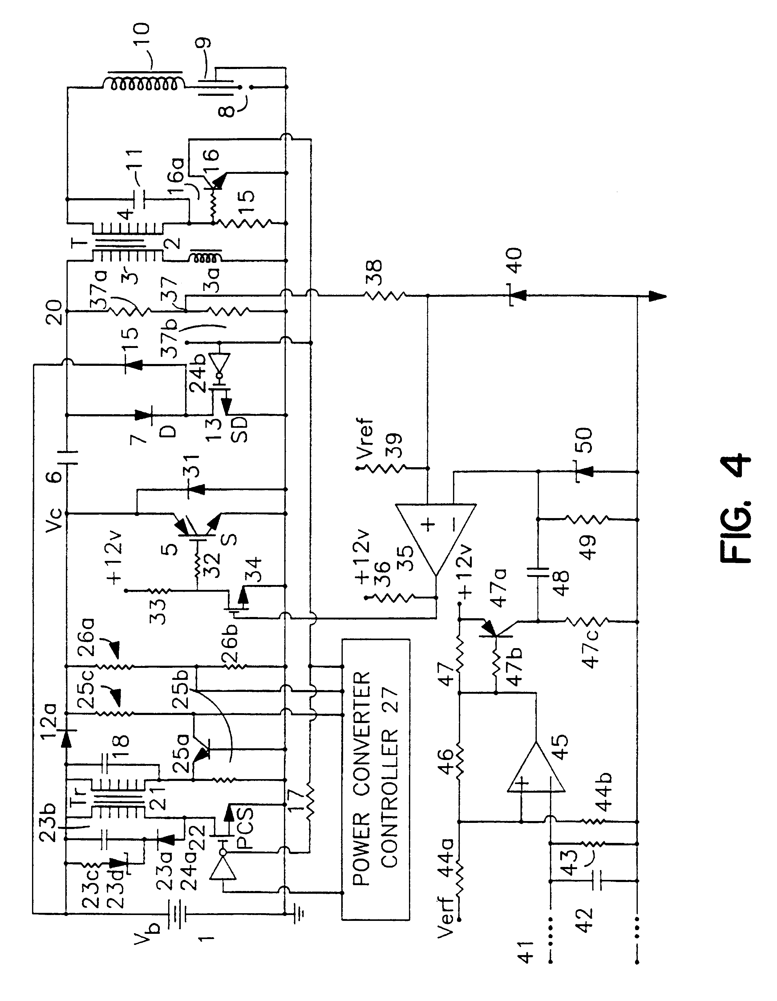
FIG. 1 is a partial block, partial circuit diagram of a topology II, CD, single coil distributor type ignition circuit, powered by a car battery 1 (voltage Vb) with ignition coil 2 (T) with primary winding 3 of turns Np and inductance Lp and coil primary leakage inductance Lpe (shown as an external inductor 3a in this figure), and secondary winding 4 of inductance Ls, with the windings 3 and 4 wound on a magnetic core. The ignition discharge circuit is fired by means of main switch 5 (S) to partially discharge capacitor 6 of capacitance Cp through current flow Ip through switch S and through the coil 2 primary winding 3, with current Ip flowing through the shunt diode D (7) upon switch S opening to produce a triangular spark current in spark gap 8 of a spark plug 9 with capacitance Cp1 either built into the spark plug or contained in a capacitive spark plug boot. Preferably, low resistance inductive spark plug wire 10 is used to suppress the capacitive spark associated with the seco...


PUM


Abstract

Capacitive discharge system for ignitors of internal combustion engines with one ignition coil (T) per ignitor with one or more capacitors (6) and shunt switch means (5) associated with each such coil, together forming a coil primary ignition circuit of Type II topology and resonance oscillation capability, each switch means being a series combination of shunt diode (D) means and switch (SD) across the coils primary winding, with a voltage drop element (Vdb) across switch SD, the system constructed to produce capacitive ignition initial spark discharge of duration less than a quarter period of the resonance oscillation of the primary ignition circuit followed by an essentially triangular distribution decaying spark discharge of longer duration than the initial discharge, with switch SD to be turned off near or after spark circuit zero to divert residual primary discharge circuit through the voltage drop element.

Description

This invention relates to capacitive discharge (CD) ignition systems for internal combustion (IC) engines, and more particularly to improved CD ignitions with much higher efficiencies and much higher spark firing rates than achievable before for a given level and type of delivered spark energy. The invention is especially useful for the very efficient and rapid delivery of high energy spark discharges of the flow-resistant type which are preferred in advanced high efficiency IC engines with high in-cylinder airflows. The invention applies to both single coil distributor type ignition systems as well as to more modern one-coil-per-plug distributorless type ignition. In the case of the distributor version, the high efficiency and high spark firing rate make the system especially useful in high speed eight cylinder (V-8) engines operating at speeds up to and above 9,000 RPM and providing the more useful flow resistant, single polarity, triangular, arc discharge mode type spark with min...

Claims


Application Information

Patent Timeline
Patent Type & Authority Patents(United States)
IPC IPC(8): F02P3/08F02P3/02F02P3/00
CPCF02P3/02F02P3/0884F02P3/0876
Inventor WARD, MICHAEL A. V.
Owner WARD MICHAEL A V
Why Eureka
Try Eureka