Electromagnetic forming of metallic glasses using a capacitive discharge and magnetic field
a capacitive discharge and magnetic field technology, applied in metal-working equipment, welding/cutting media/materials, soldering media, etc., can solve the problems of limited use of early amorphous alloys as bulk objects and articles, limited size of early amorphous alloys, and inconvenient casting processes. achieve the effect of high permeability soft magnetic cor
- Summary
- Abstract
- Description
- Claims
- Application Information
AI Technical Summary
Benefits of technology
Problems solved by technology
Method used
Image
Examples
example 1
Molding
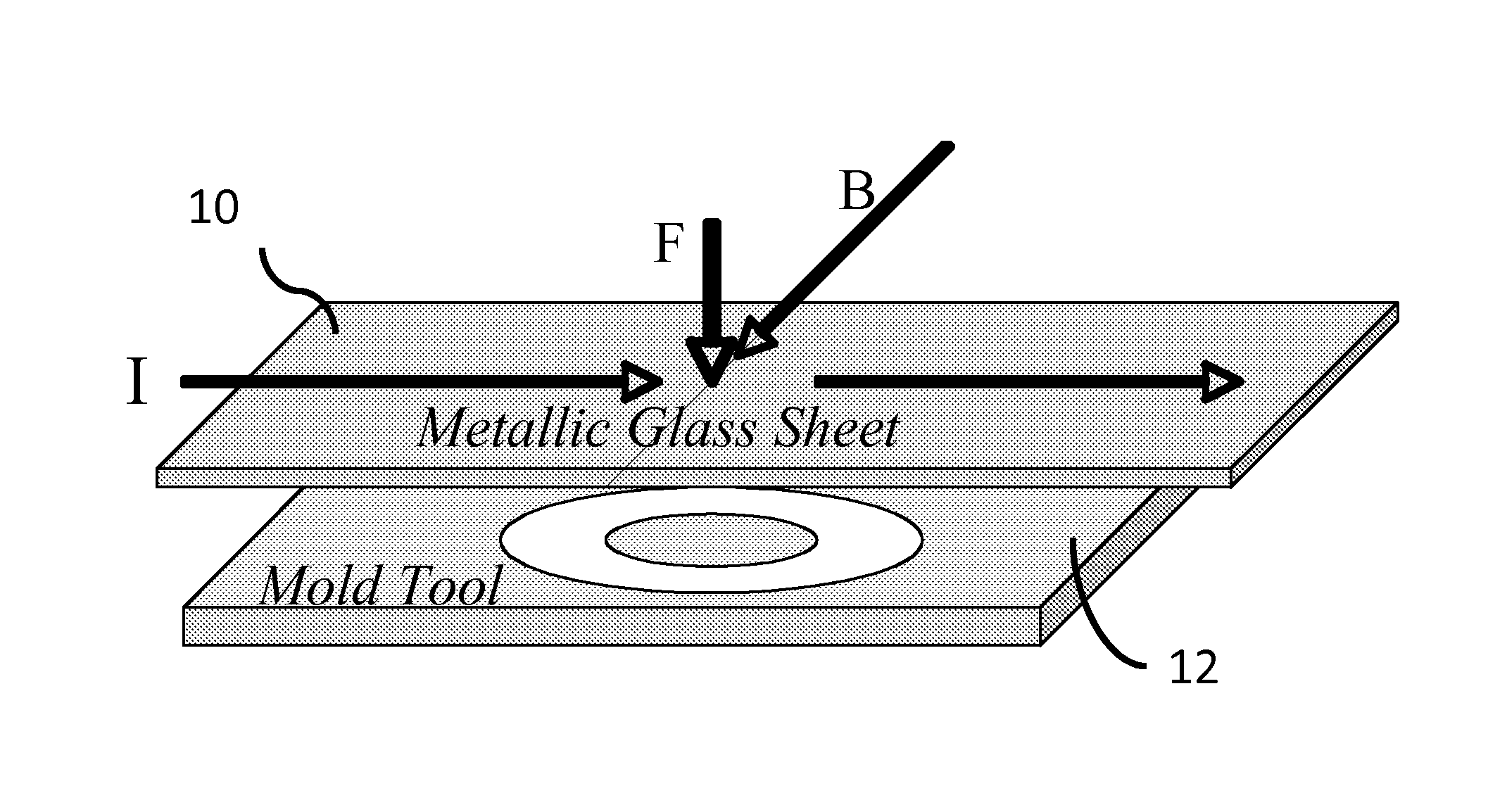
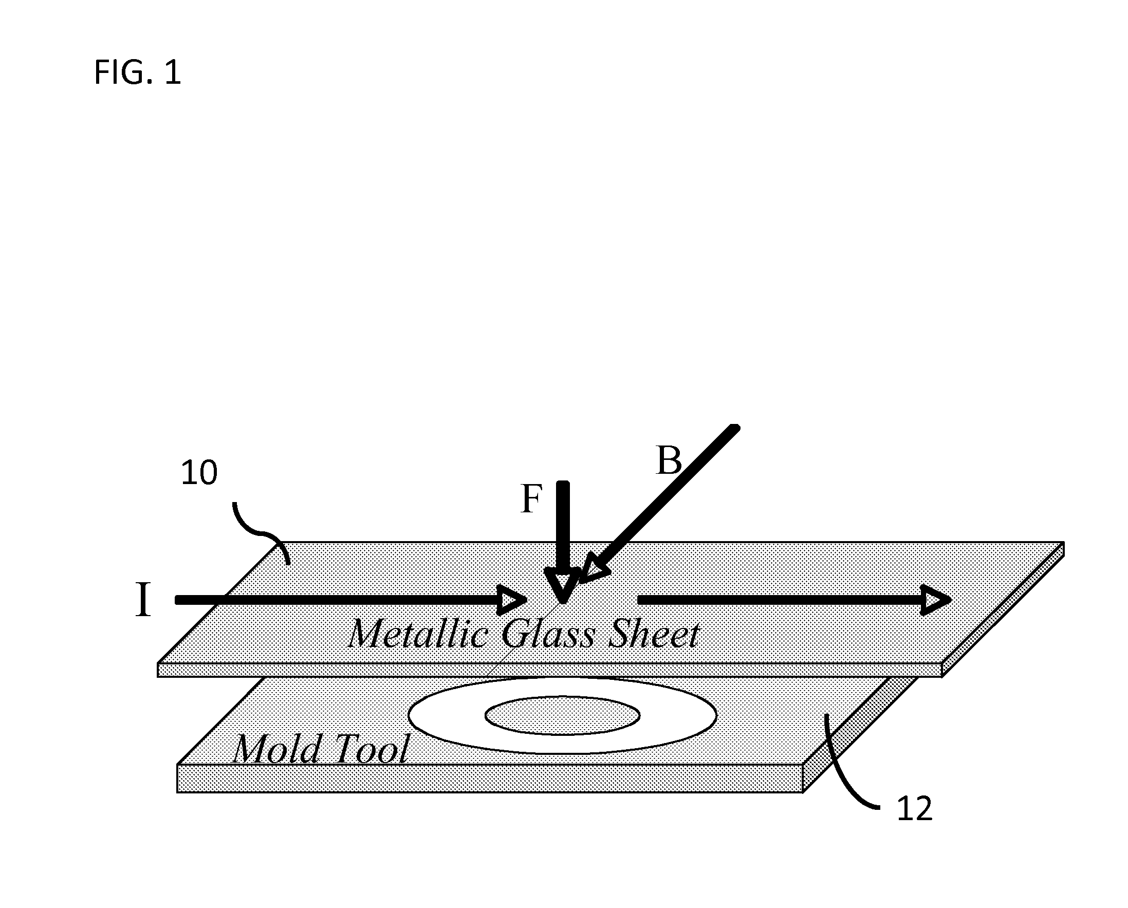
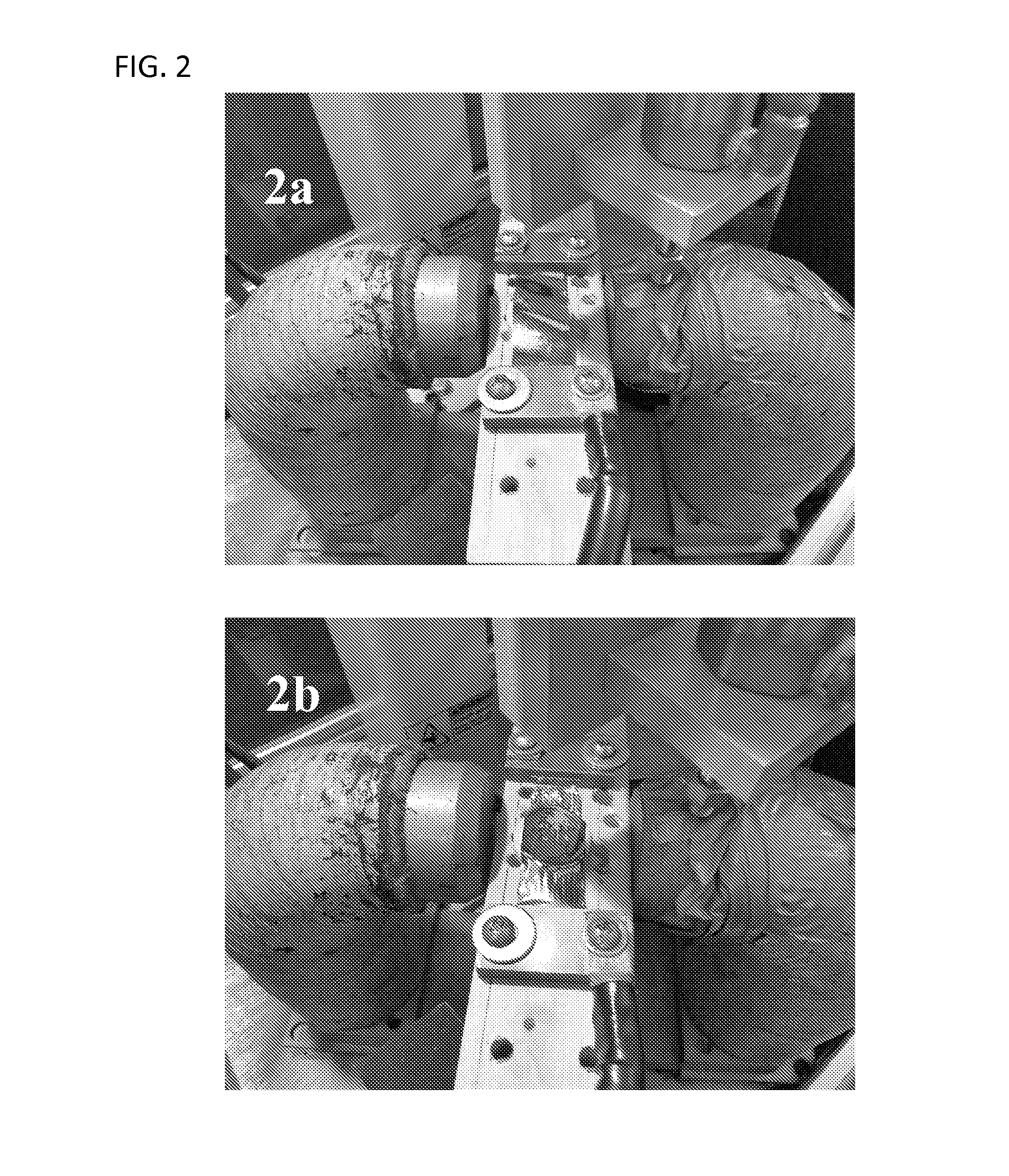
[0068]As a demonstration of the method in a simple molding case, a thin sheet of metallic glass (Metglas MBF 50—Ni-based brazing alloy) produced by planar flow casting is used. The sheet is in the form of a ribbon of width 1-2″, thickness of about 30-40 μm. Such ribbons are commercially available in long lengths from the Metglas Division of Hitachi Metals. A 0.262 Farad capacitor band controlled by a silicon rectifier was used. A simple demonstration die tool was fabricated from a machinable ceramic, Macor. For demonstration, a Macor die of circular symmetry with concentric grooves machined in the surface was chosen as shown in FIGS. 2A to D.
[0069]A reasonably homogeneous magnetic field of ˜1 kG was applied in the region surrounding the mold and was provided by a permanent magnet as seen in FIGS. 2A and 2B. The capacitor was charged to voltages in the range of 20-40 volts and discharged through copper leads and a copper clamping strip on the ribbon. FIG. 2A shows the original...
example 2
Sheet Forming
[0071]FIG. 3 shows an exemplary set-up for a method of forming sheets from a plate using twin rolls. As shown, in this embodiment an electromagnetic force (F) is exerted on a square or rectangular bar (14) of metallic glass located above the gap between two rotating rollers (16). The electrical discharge (I) is transferred to the sample by electrodes (not shown), which contact the ends of the bar (14). Current is induced along the length of the bar. A static magnetic field (B) is applied normal to the bar (14) and parallel to the plane defined by the two axes (18) of the twin rollers (16). The electromagnetic force drives the heated bar into the gap between the rollers to produce a rolled sheet. The bar may be contained in a vertical channel (not shown) made of electrically non-conducting material in order to confine and efficiently guide the material through the rollers.
example 3
Injection Molding & Extrusion of a Net-Shaped Component
[0072]In another embodiment, the basic method may be used to injection mold a square rod into a mold cavity of net-shape. As shown in FIG. 4, in this embodiment an electromagnetic force (F) can be used to create a pressure gradient along the length of a metallic glass sample (20) during discharge heating of the rod by a current (I) across its width provided by two bar shaped electrodes (22). To prevent leakage, the charge is confined by non-conducting containment walls (24). A mold tool with suitable gating and mold cavity can be provided (not shown) that would then be filled by the injected liquid as it is heated to a suitable process temperature (as described above).
[0073]Alternatively, the same set-up can be used for a method of extrusion of a net-shaped component of uniform cross-section using an extrusion die. In this embodiment, the apparatus is used to force a heated charge of metallic glass through an extrusion die. In t...
PUM
| Property | Measurement | Unit |
|---|---|---|
| viscosity | aaaaa | aaaaa |
| discharge time constant | aaaaa | aaaaa |
| discharge time constant | aaaaa | aaaaa |
Abstract
Description
Claims
Application Information
 - R&D
- Intellectual Property
- Life Sciences
- Materials
- Tech Scout
- Unparalleled Data Quality
- Higher Quality Content
- 60% Fewer Hallucinations
Browse by: Latest US Patents, China's latest patents, Technical Efficacy Thesaurus, Application Domain, Technology Topic, Popular Technical Reports.
© 2025 PatSnap. All rights reserved.Legal|Privacy policy|Modern Slavery Act Transparency Statement|Sitemap|About US| Contact US: help@patsnap.com


