Method and apparatus for calibrating X-ray detectors in a CT-imaging system

a technology of ct imaging and detectors, applied in tomography, applications, instruments, etc., can solve the problems of reducing patient throughput, increasing imager down time, and changing the gain ratio of detectors in ct imaging, and degrading the image provided by the ct imaging

Inactive Publication Date: 2009-01-13
KONINKLIJKE PHILIPS ELECTRONICS NV
View PDF2 Cites 13 Cited by
  • Summary
  • Abstract
  • Description
  • Claims
  • Application Information

AI Technical Summary

Benefits of technology

[0023]An aspect of some embodiments of the present invention relates to providing a method for updating values for gain ratio factors of a CT-imager during run time of the imager by updating the imager's differential gain ratio factors without having to perform an air-calibration of the imager.
[0024]During normal imaging procedures with a CT-imager, often during a scanning procedure performed to image a patient, for a portion of the procedure, the CT-imager's X-ray source illuminates the detector array when there is nothing located between the X-ray source and the detector array. Absorption data generated during such portions of a scan, hereinafter referred to as “blank portions”, provides the same type of as data generated during a conventional air-calibration. In accordance with an embodiment of the present invention the data is used to update the imager's gain ratio factors. Updating is therefore achieved using run time data generated during CT-scans of patients that are normally performed to acquire CT-images of the patients. As a result updating, in accordance with an embodiment of the present invention, does not interfere with or interrupt the normal work-flow of CT-imaging patients and does not increase down time of the imager.

Problems solved by technology

Whereas an air-calibration may be performed as frequently as a few times a day, performing an air-calibration once CT-imaging of patients has begun, increases imager down time and decreases patient throughput.
However, during a day's operation of a CT-imager, gain ratios of detectors in the CT-imager often change as a result of changes in sensitivity of the detectors due, for example, to temperature changes and radiation damage and changes in communication links that transmit data from the detectors mounted on the gantry rotor to the gantry's stator.
Such changes can degrade images provided by the CT-imager by, for example, generating ring artifacts in the images.
Whereas, values for AC(n) of a CT-imager may be corrected, as noted above, by correcting average gain ratio factors AC responsive to average gain ratios determined for non-shadowed detectors, the corrections thus made do not correct for changes in the differential gain ratio factors ΔAC(n) of the imager.
As a result, quality of CT-images acquired with the imager during a day's operation can be compromised by ring artifacts and other image defects.

Method used


Image

  • Method and apparatus for calibrating X-ray detectors in a CT-imaging system
  • Method and apparatus for calibrating X-ray detectors in a CT-imaging system
  • Method and apparatus for calibrating X-ray detectors in a CT-imaging system

Examples


Embodiment Construction

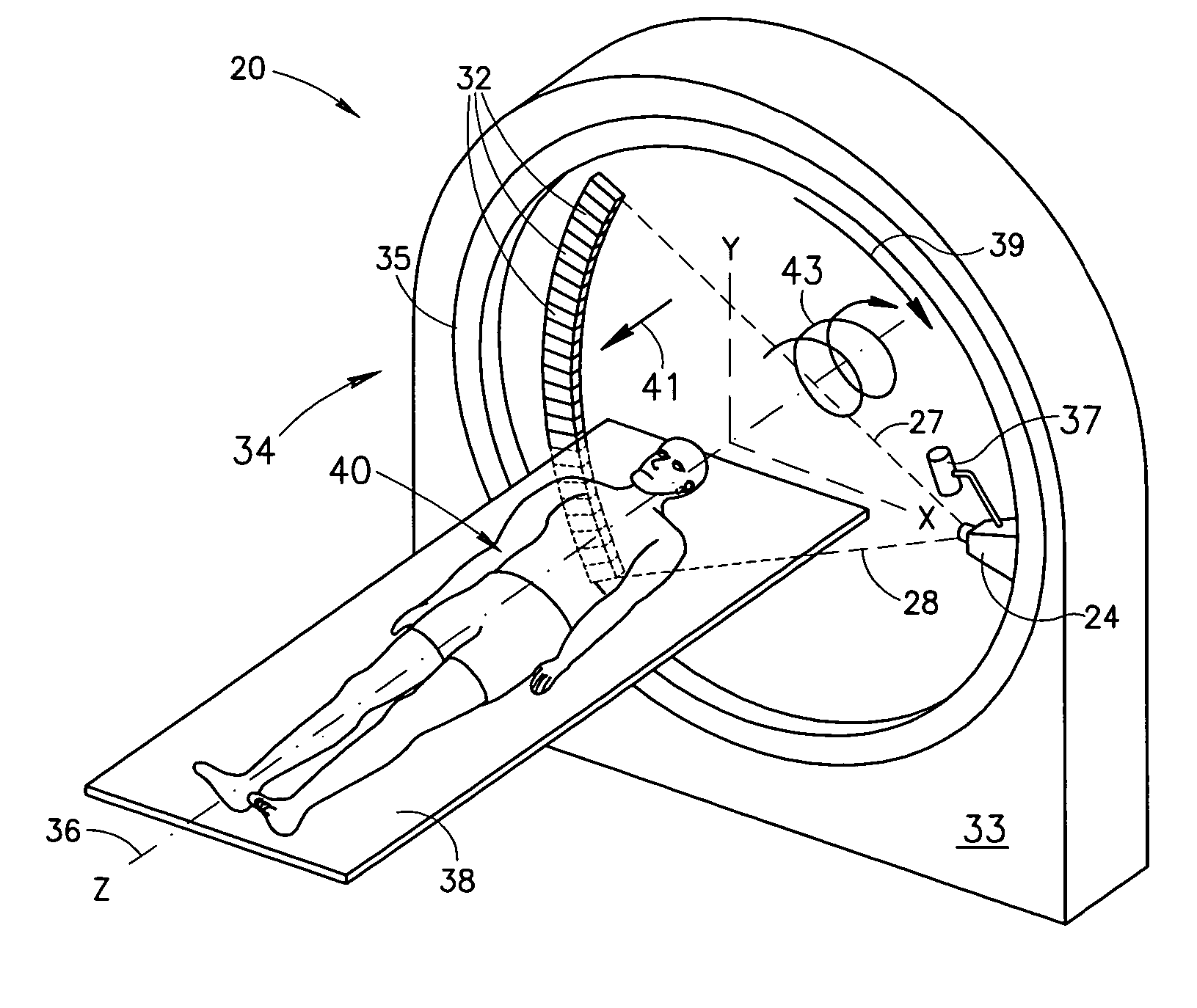
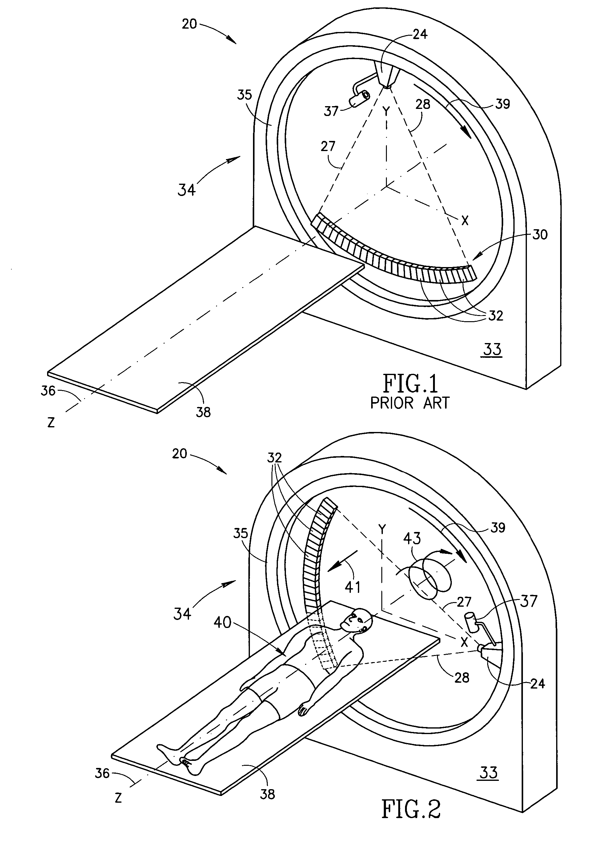
[0073]FIG. 1 schematically shows a CT-imager 20 being air-calibrated to determine gain ratio factors, in accordance with prior art.

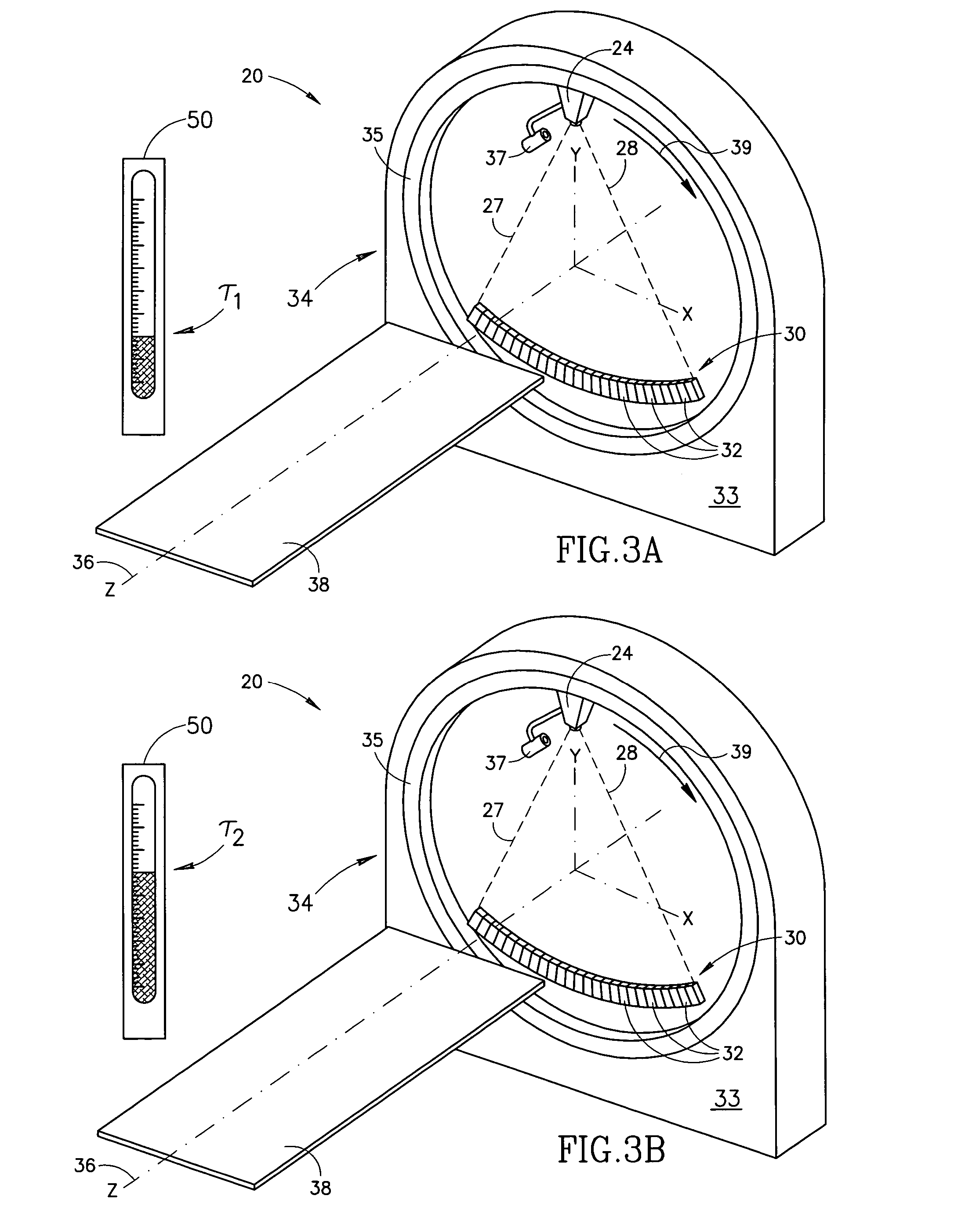
[0074]CT-imager 20 comprises an X-ray source 24 controllable to provide a fan-beam schematically indicated by dashed lines 27 and 28 and an array 30 of X-ray detectors 32 opposite the X-ray source for sensing X-rays in the fan-beam. CT-imager 20 comprises a gantry 34 having a stator 33 to which a rotor 35 is mounted so that the rotor can be controlled to rotate about an axis 36. X-ray source 24 and detector array 30 are rigidly mounted to rotor 35 so that when rotor 35 rotates about axis 36 the X-ray source and detector array also rotate about the axis. CT-imager 20 is shown, by way of example, as a single slice imager and array 30 has, accordingly, a single row of detectors in array 30. It is noted however that the present invention is not limited to single slice CT-imagers. Embodiments of the present invention may be practiced with multislice CT-scanne...


PUM


Abstract

A method of adjusting values for sensitivities of X-ray detectors comprised in a CT-imager that generate signals responsive to X-rays from an X-ray source in the imager, comprising: acquiring signals generated by X-ray detectors in the CT-imager responsive to X-rays incident thereon from the X-ray source for views taken during a scanning procedure performed by the CT-imager to image a patient when only air is present in a space between the X-ray source and the detectors; and using the signals to adjust the values of the sensitivities.

Description

FIELD OF THE INVENTION[0001]The present invention relates to computerized tomography (CT) X-ray imaging, and in particular to methods for calibrating X-ray detectors comprised in a CT-imaging system.BACKGROUND OF THE INVENTION[0002]In CT X-ray imaging of a patient, X-rays are used to image internal structure and features of a region of the patient's body. The imaging is performed by a CT-imaging system, hereinafter referred to as a “CT-imager”, which images internal structure and features of a plurality of contiguous relatively thin planar slices of the body region using X-rays.[0003]The CT-imager generally comprises an X-ray source that provides a planar, fan-shaped X-ray beam and an array of X-ray detectors that are coplanar with the fan beam and face the X-ray source. The X-ray source and array of detectors are mounted in a gantry so that a patient being imaged with the imager, generally lying on an appropriate support couch, can be positioned in a space within the gantry between...

Claims


Application Information

Patent Timeline
Patent Type & Authority Patents(United States)
IPC IPC(8): G01D18/00A61B6/03
CPCA61B6/032A61B6/585
Inventor BRAUNSTEIN, DAVID
Owner KONINKLIJKE PHILIPS ELECTRONICS NV
Why Eureka
Try Eureka