Infrared camera system and method

a camera system and infrared technology, applied in the field of imaging systems, can solve the problems that video images obtained using visible light may not reveal prohibited materials carried by the subject or may be insufficient for further analysis

Active Publication Date: 2009-01-13
CUCCIAS FRANK J
View PDF25 Cites 83 Cited by
  • Summary
  • Abstract
  • Description
  • Claims
  • Application Information

AI Technical Summary

Benefits of technology

[0018]The IR camera system and method of the present invention have a number of applications and the IR pass filtered images obtainable therewith achieve a number of advantages over visible light images such as allowing a user to see into or see through vehicles with tinted windows, clothing, and sunglasses. State troopers and local law enforcement may utilize such IR camera systems when pulling over a vehicle having heavily tinted windows. The IR imaging capability of the IR camera systems permits a user thereof to see into the vehicle either during the day or at night so that they may observe the occupants of the vehicle before and while approaching the vehicle. The IR pass filtered image can either automatically fine-tune itself to see into the vehicle or be manually controlled to detect potential threats such as armed or hostile occupants. IR camera systems in accordance with the present invention also have the ability to see through various types of clothing fabrics such as wool, cotton, synthetics, and blends. This permits potentially threatening objects such as bullet-proof vests, weapons (knives, guns, etc.), documents, illegal substances, or even hidden messages under a person's clothing to be observed. The ability of the IR camera systems of the present invention to obtain an image of a person's eyes through various types of sunglasses (polarized, non-polarized, and mirrored) make such IR camera systems particularly suited for supporting facial biometrics applications.

Problems solved by technology

Often times, however, video images obtained using visible light may not reveal prohibited materials carried by the subject or may be insufficient for further analysis.

Method used


Image

  • Infrared camera system and method
  • Infrared camera system and method
  • Infrared camera system and method

Examples


Embodiment Construction

IR Camera Systems

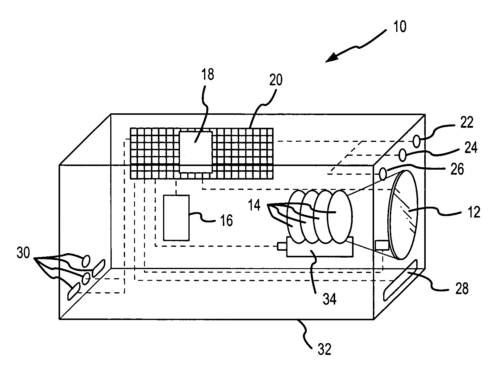
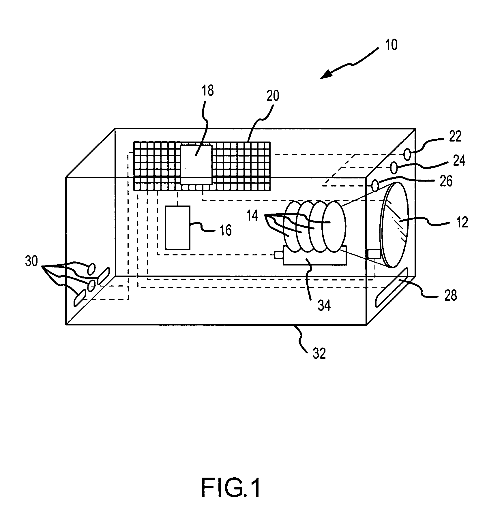
[0030]Referring to FIG. 1, there is shown one embodiment of an IR camera system 10. The IR camera system 10 includes a lens 12, a number of IR pass filters 14, an optical detector 16, a processor 18 mounted on a circuit board 20, a distance sensor 22, a visible light sensor 24, an IR light sensor 26, an IR illuminator 28, and a number of video outputs 30 (e.g., component video, serial, s-video, firewire), all of which may be disposed within an appropriately configured housing 32. Additional components (not shown) such as, for example, one or more digital-to-analog converters and analog-to-digital converters for interfacing the processor 18 with other components of the IR camera system 10, one or more memory devices (e.g., RAM and / or ROM), and other components, may also be mounted on the circuit board 20. The IR camera system 10 may also include multiple power supply options (not shown) such as, for example, DC, AC, and battery with a mini-solar panel for recharging ...


PUM


Abstract

Infrared (IR) camera systems for and a method of obtaining infrared images of target subjects are provided. In one embodiment, an IR camera system (10) includes a lens (12), a number of IR pass filters (14), an optical detector (16), a processor (18) mounted on a circuit board (20), a distance sensor (22), a visible light sensor (24), an IR light sensor (26), an IR illuminator (28), and a number of video outputs (30), all of which may be disposed within an appropriately configured housing (32). The filters (14) are mounted on a juke-box like rack system (34) also included within the housing (32). The processor (18) determines which pass filter is needed in order to optimize the image and sends an electronic signal to the rack system (34) directing the rack system (34) to move the appropriate filter (14) into the optical pathway between the lens (12) and the optical detector (16) and pull all of the other IR filters (14) out of the optical pathway between the lens (12) and the optical detector (16).

Description

RELATED APPLICATION INFORMATION[0001]This application claims priority from U.S. Provisional Application Ser. No. 60 / 394,852 filed on Jul. 10, 2002, and entitled “SYSTEM AND METHOD FOR ACQUIRING, TRANSMITTING AND PROCESSING LIVE AUDIO AND INFRARED VIDEO SIGNAL DATA USING THE LMX-CAM SYSTEM”, the entire disclosure of which is incorporated herein.FIELD OF THE INVENTION[0002]The present invention relates generally to imaging systems, and more particularly to obtaining enhanced images using infrared (IR) optical energy.BACKGROUND OF THE INVENTION[0003]There are a number of situations wherein it is desirable to obtain video images of target subjects (e.g., persons, vehicles). Such situations include, for example, law enforcement contact with suspects, airport security checkpoints, building and public event access, and the like. Often times, however, video images obtained using visible light may not reveal prohibited materials carried by the subject or may be insufficient for further analy...

Claims


Application Information

Patent Timeline
Patent Type & Authority Patents(United States)
IPC IPC(8): H04N9/64H04N5/225H04N5/33
CPCH04N5/2254H04N5/33H04N23/55H04N23/661H04N23/671H04N23/63H04N23/125
Inventor CUCCIAS, FRANK J.
Owner CUCCIAS FRANK J
Why Eureka
Try Eureka