
Variable rate channel quality feedback in a wireless communication system

Active Publication Date: 2009-01-13
WSOU INVESTMENTS LLC +1
View PDF14 Cites 20 Cited by
  • Summary
  • Abstract
  • Description
  • Claims
  • Application Information

AI Technical Summary

Benefits of technology

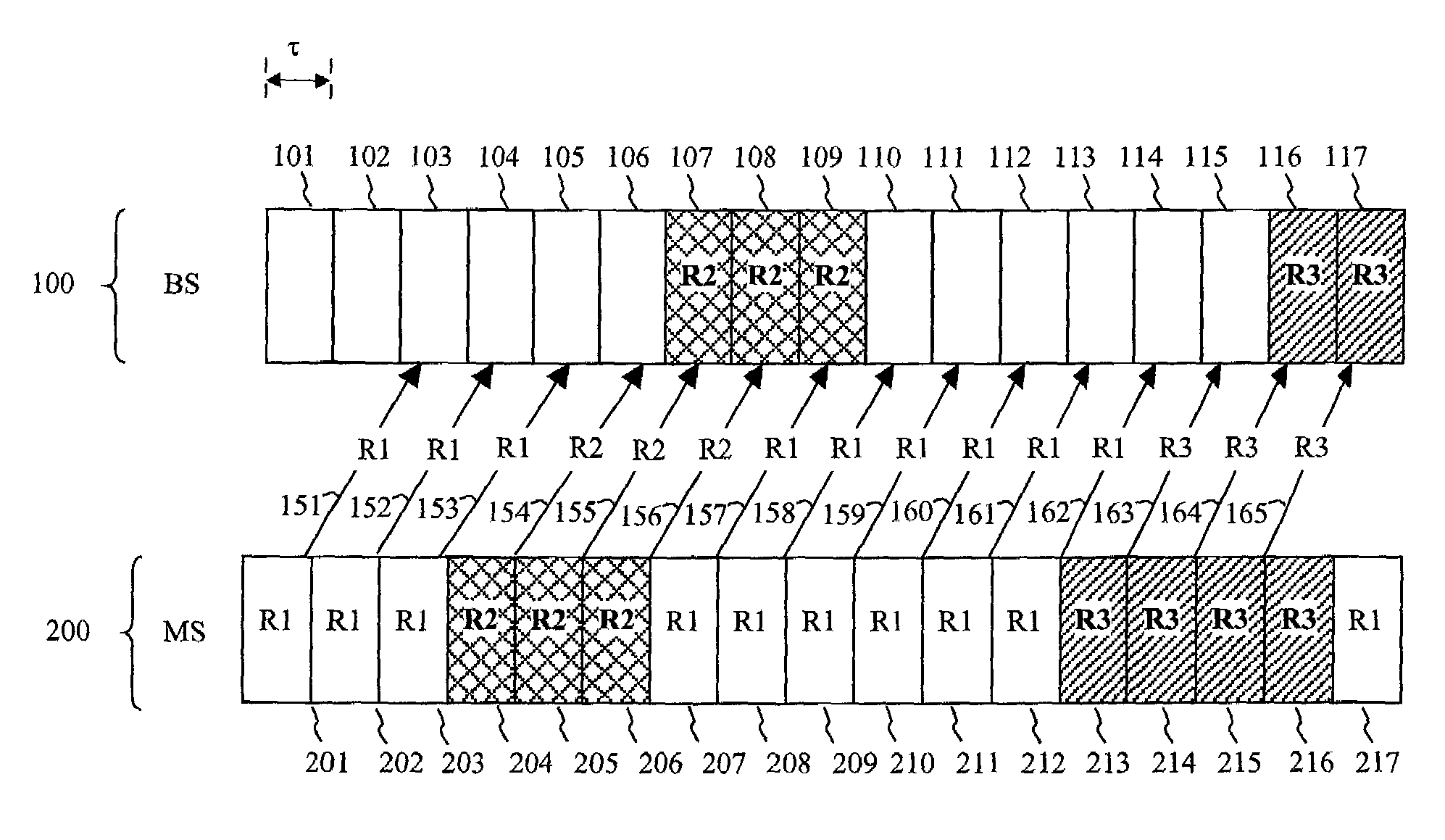
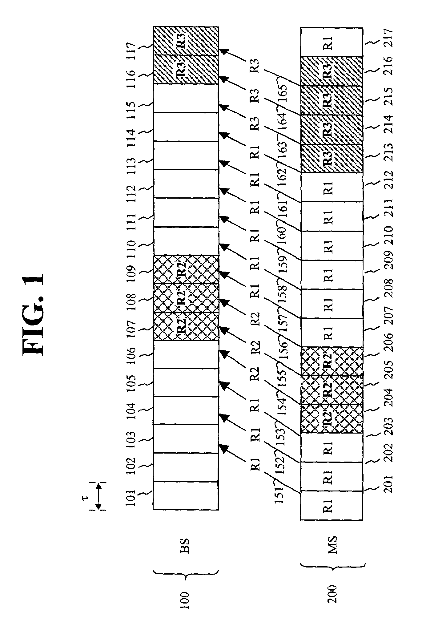
[0008]Processing overhead for rate calculation / prediction and transmission overhead for rate feedback is substantially reduced for wireless transmissions according to the principles of the invention by varying the feedback rate for reporting channel quality information from a mobile station to a base station as a function of the presence or absence of a transmission from the base station to the mobile station. More specifically, channel quality feedback is provided from the mobile station to the base station at a variable rate such that the feedback rate is faster when the base station is transmitting to the mobile station and slower when there is no transmission occurring.
[0009]Wireless resources can be more efficiently used since the rate at which the mobile station reports channel quality to the base station is varied as a function of the absence or presence of transmission from the base station. When the base station is not transmitting to the mobile station, the feedback rate for reporting channel quality from the mobile station is at a slower rate, which, in turn, frees up wireless resources that can be used for other purposes, e.g., for transmissions between the mobile station and the base station. When the base station is transmitting to the mobile station, the rate of reporting channel quality from the mobile station is increased so that rate adaptation can be carried out more accurately by the base station. Moreover, because of the short duration of time slots in wireless transmission, it is highly unlikely that the rate or channel quality will change over a period of a few time slots under most operating conditions.

Problems solved by technology

Moreover, because of the short duration of time slots in wireless transmission, it is highly unlikely that the rate or channel quality will change over a period of a few time slots under most operating conditions.

Method used


Image

  • Variable rate channel quality feedback in a wireless communication system
  • Variable rate channel quality feedback in a wireless communication system
  • Variable rate channel quality feedback in a wireless communication system

Examples


Embodiment Construction

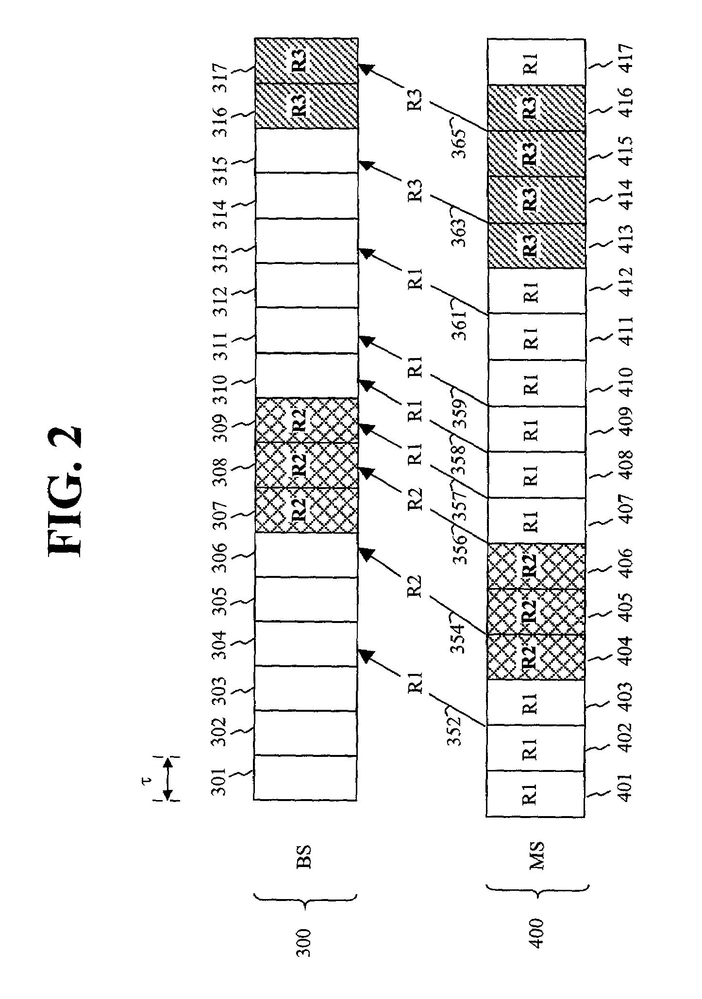
[0014]FIG. 2 shows one exemplary embodiment for providing variable rate channel quality feedback according to the principles of the invention. By way of example only, this scheme will be described in the context of wireless transmission according to the 1x-EV-DO (data only) standard, but the teachings set forth herein are not at all limited to just this particular wireless implementation.

[0015]More specifically, FIG. 1 shows a signaling diagram between a base station (BS) and a mobile station (MS). The data channel 300 for the downlink from the base station to the mobile station is divided into time slots 301-317, each of which has a duration τ, e.g., 1.67 milliseconds. In the example shown in FIG. 2, time slots 301-306 and 310-315 are not carrying transmissions from the base station to the mobile station. However, the base station is transmitting to the mobile station during time slots 307-309 and during time slots 316-317. From the perspective of the mobile station, the uplink con...


PUM


Abstract

A channel quality feedback method for wireless transmission is described in which the rate for reporting channel quality information from a mobile station to a base station is variable as a function of the presence or absence of a transmission from the base station to the mobile station. In particular, the feedback rate from the mobile station to the base station is increased when the mobile station detects a transmission from the base station. As such, the feedback rate is slower when there is no data transmission for the mobile station and faster when the mobile station is receiving data.

Description

TECHNICAL FIELD[0001]The invention relates generally to wireless communication systems and, more particularly, to providing channel quality information from a mobile station to a base station in such systems.BACKGROUND OF THE INVENTION[0002]In wireless communication systems, an air interface is used for the exchange of information between a mobile station and a base station or other communication system equipment. The air interface typically comprises a plurality of communication channels. In wireless transmission, a channel is time varying due to fading, mobility, and so on. More specifically, channel quality is affected by factors such as distance between the mobile and base station, speed of the mobile station, interference, and the like. Given the limited resources (e.g., bandwidth) of wireless transmission as well as the large number of mobile stations supported by a base station at any given time and therefore competing for those limited resources, it is therefore important to...

Claims


Application Information

Patent Timeline
IPC IPC(8): H04B17/02H04B17/40H04B7/26H04L1/00H04L1/12H04L1/18H04M3/00H04Q7/20
CPCH04L1/0001H04L1/0026H04L1/0027H04L1/0003H04L1/0009H04L1/12H04L1/18H04L2001/0093
Inventor DAS, AMABKHAN, FAROOQ ULLAH
Owner WSOU INVESTMENTS LLC
Learn More