
Cooling fan using Coanda effect to reduce recirculation

a cooling fan and coanda technology, applied in the direction of machines/engines, stators, liquid fuel engines, etc., can solve the problems of no work or other useful function being accomplished, leakage represents a loss of efficiency, etc., and achieve the effect of reducing the tendency of exhaus

Active Publication Date: 2009-01-20
VALEO INC
View PDF25 Cites 131 Cited by
  • Summary
  • Abstract
  • Description
  • Claims
  • Application Information

AI Technical Summary

Benefits of technology

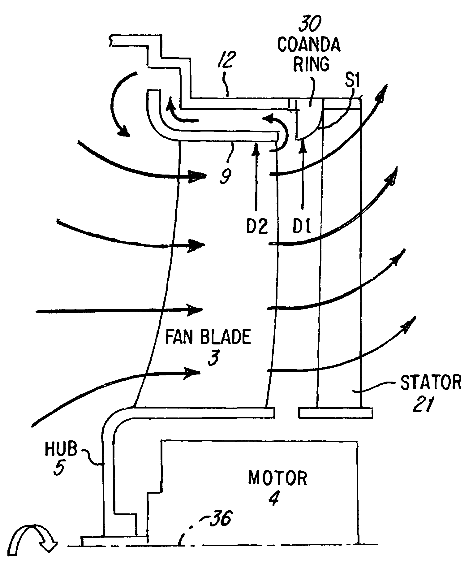
[0007]In one form of the invention, a duct of increasing cross-sectional area is positioned in the exhaust of a fan, and upstream of stators used to straighten flow. Exhaust of the fan adheres to the walls of the duct because of the Coanda Effect, thereby reducing tendencies of the exhaust to reverse direction and leak upstream, past the tips of the fan blades.
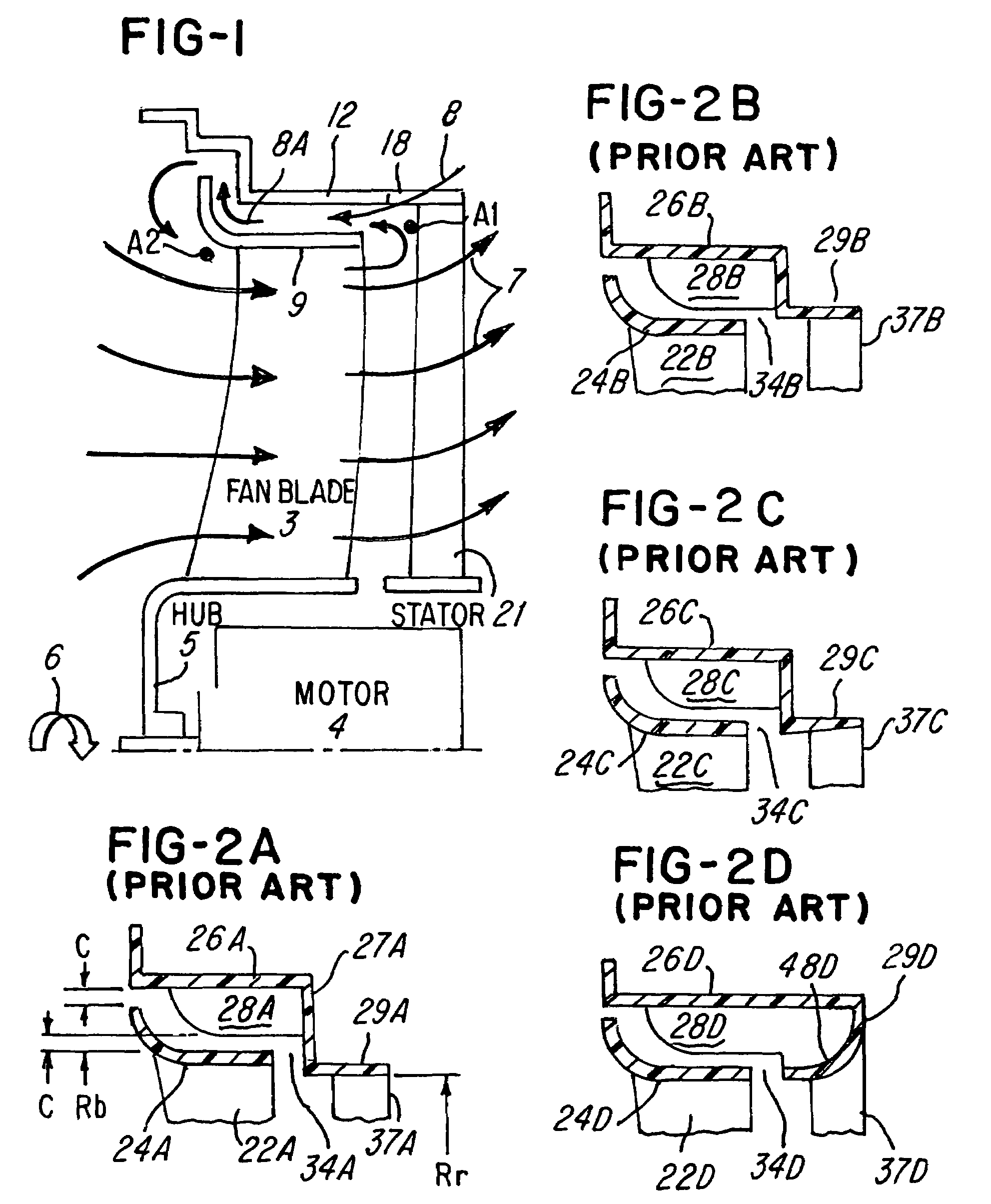
[0009]A further object of the invention is to provide a cooling fan in a motor vehicle which employs the Coanda effect to entrain high pressure air in a flow path to thereby reduce the leakage illustrated in FIG. 1.
[0010]In one aspect, one embodiment comprises a cooling system for a vehicle, comprising: a fan which produces exhaust which enters stator vanes downstream; and means, located entirely between the fan and the stator vanes, which increases fan efficiency. In one embodiment, efficiency is increased by at least three percent.
[0011]In another aspect, one embodiment comprises a cooling system for a vehicle, comprising: a fan which produces exhaust which includes a leakage flow, which leaks upstream of the fan, past blades of the fan; and means downstream of the fan, which reduces the leakage flow.
[0013]In still another aspect, one embodiment comprises a cooling system for a vehicle, comprising: a fan having an exit diameter D; a duct immediately downstream of the fan, having an inlet diameter equal to D; and an exit diameter greater than D, which duct reduces torque required to power the fan.

Problems solved by technology

This leakage represents a loss in efficiency, since the leaked air was initially pumped or moved to the pressure at point A1, but then drops to the pressure at point A2, but with no work or other useful function being accomplished.

Method used


Image

  • Cooling fan using Coanda effect to reduce recirculation
  • Cooling fan using Coanda effect to reduce recirculation
  • Cooling fan using Coanda effect to reduce recirculation

Examples


Embodiment Construction

[0032]FIG. 4 is a cross-sectional view of one form of the invention, wherein an annular ring 30, termed a Coanda ring, is stationed downstream of the fan ring 9, and upstream of stator 21. The fan ring 9 is a ring which connects the tips of neighboring fan blades.

[0033]The inner diameter D1 of the Coanda ring 30 is equal to the inner diameter D2 of the fan ring 9. Further, as shown in FIG. 5, the inner surface 33 of the Coanda ring 30, at the point P1 where fan exhaust enters the Coanda ring 30, is tangent to the fan airflow 34. The inner surface 33 of the Coanda ring 30 then curves away from the central axis 36 in FIG. 4 of the fan, acting somewhat as a diffuser, but while maintaining attached flow along the Coanda ring 30, as discussed later.

[0034]The Coanda ring 30 utilizes the Coanda effect. The Coanda effect can be easily demonstrated, using an ordinary water faucet and a water glass, held horizontally, both shown in FIGS. 6A and 6B. On the left side of FIG. 6A, the water glass...


PUM


Abstract

A cooling fan for an engine in a vehicle. Ordinarily, a fan rotates within a shroud, which surrounds the fan. Leakage can occur between the tips of the fan blades and the shroud, wherein fan exhaust moves forward, and then passes through the fan again. The invention reduces leakage by placing a surface downstream of the fan. The surface employs the Coanda Effect, to urge fan exhaust to continue in the downstream direction, and not move forward as leakage air.

Description

[0001]The invention concerns an approach to reducing air which leaks upstream past fan blades that are moving air downstream.BACKGROUND OF THE INVENTION[0002]FIG. 1 is a cross-sectional view of a prior-art cooling fan 3, as used in motor vehicles, which cools a radiator (not shown), which extracts heat from engine coolant. A motor 4 rotates a cylindrical hub 5, as indicated by arrow 6, which hub 5 carries fan blades 3. Arrows 7 indicate moving air streams.[0003]One feature of such a fan is that it increases static pressure at point A1, compared with point A2. This pressure differential causes leakage air, indicated by arrows 8 and 8A, to flow in the space between the fan ring 9 and the shroud 12.[0004]This leakage represents a loss in efficiency, since the leaked air was initially pumped or moved to the pressure at point A1, but then drops to the pressure at point A2, but with no work or other useful function being accomplished.[0005]It may appear that the airflow indicated by arrow...

Claims


Application Information

Patent Timeline
Patent Type & Authority Patents(United States)
IPC IPC(8): F04D29/54
CPCF04D29/547
Inventor HONG, TAOSAVAGE, JOHN R
Owner VALEO INC
Learn More