Hybrid architecture incorporating three motor generators and brakes

a hybrid vehicle and generator technology, applied in the direction of electric propulsion mounting, electric propulsion, transportation and packaging, etc., can solve the problems of limited market penetration, the size of the electric motor, and the cost of the hybrid vehicle is the power capacity of the battery, so as to reduce the need for massive and expensive energy storage and minimize the operation of the motor/generator

Inactive Publication Date: 2009-01-20
GM GLOBAL TECH OPERATIONS LLC
View PDF10 Cites 70 Cited by
  • Summary
  • Abstract
  • Description
  • Claims
  • Application Information

AI Technical Summary

Benefits of technology

[0003]This invention describes continuously-variable hybrid transmissions that utilize a combination of planetary gear sets, electric motor / generators and brakes to offer multi-mode EVTs with capability for series hybrid reverse driving, thus reducing the need for massive and expensive energy storage (battery), and to minimize operating the motor / generators under highly inefficient conditions. In the series hybrid reverse driving mode, power from the engine is used to drive at least one of the motor / generators to generate electric power, and the generated electric power is delivered to at least one of the other motor / generators to drive the vehicle in the forward or reverse direction. This capability eliminates the need for significant power from the battery to drive the vehicle in reverse, as is currently the case.
[0004]The electrically variable transmission family of the present invention provides low-content, low-cost electrically variable transmission mechanisms including first and second differential gear sets, a battery (or similar energy storage device), three electric machines serving interchangeably as motors or generators and up to three brakes. Preferably, the differential gear sets are planetary gear sets, but other gear arrangements may be implemented, such as bevel gears or differential gearing to an offset axis.

Problems solved by technology

Electric hybrid vehicles offer the potential for significant fuel economy improvements over their conventional counterparts; however, their market penetration is limited because of their relatively high cost / benefit ratio.
Two of the contributors to the cost of the hybrid vehicle are the energy storage (battery) power capacity and the size of the electric motor / generators required to realize all-electric reverse in many electric-variable-transmission (EVT)-based hybrid systems.

Method used


Image

  • Hybrid architecture incorporating three motor generators and brakes
  • Hybrid architecture incorporating three motor generators and brakes
  • Hybrid architecture incorporating three motor generators and brakes

Examples


second exemplary embodiment

DESCRIPTION OF A SECOND EXEMPLARY EMBODIMENT

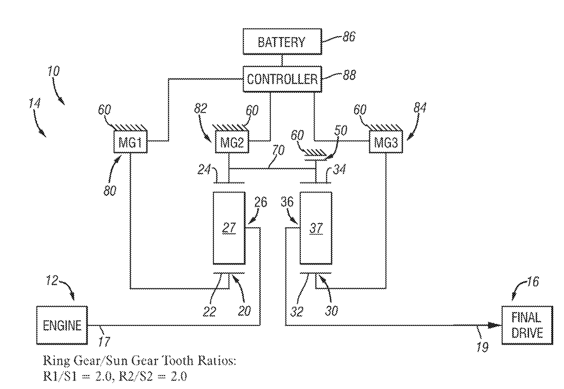
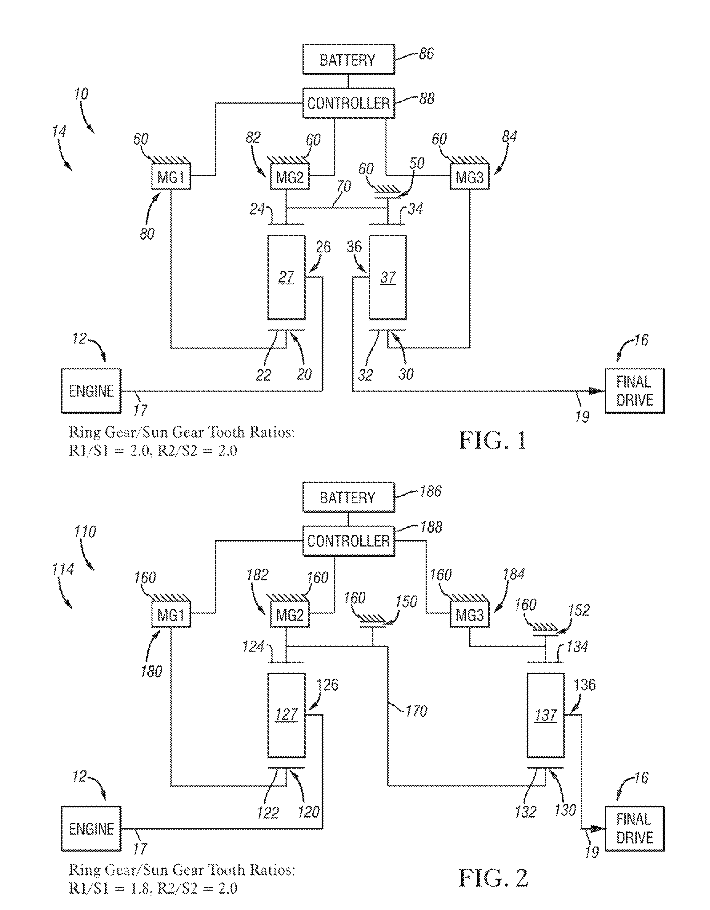
[0044]With reference to FIG. 2, a powertrain 110 is shown, including an engine 12 connected to another embodiment of the improved electrically variable transmission (EVT), designated generally by the numeral 114. Transmission 114 is designed to receive at least a portion of its driving power from the engine 12. As shown, the engine 12 has an output shaft that serves as the input member 17 of the transmission 114. A transient torque damper (not shown) may also be implemented between the engine 12 and the input member 17 of the transmission.

[0045]In the embodiment depicted the engine 12 may be a fossil fuel engine, such as a gasoline or diesel engine which is readily adapted to provide its available power output typically delivered at a selectable number of revolutions per minute (RPM).

[0046]Irrespective of the means by which the engine 12 is connected to the transmission input member 17, the transmission input member 17 is operatively conne...

third exemplary embodiment

DESCRIPTION OF A THIRD EXEMPLARY EMBODIMENT

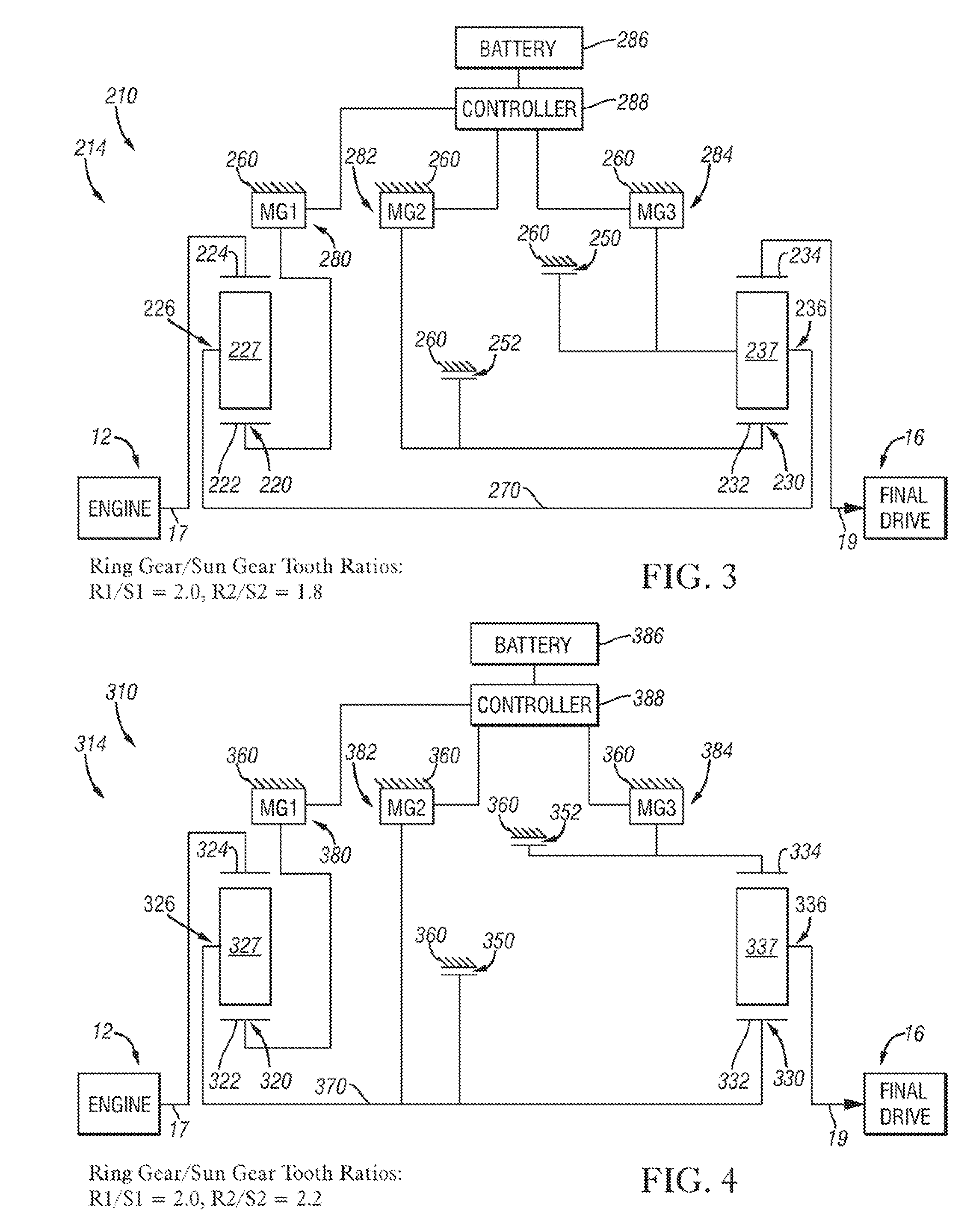
[0057]With reference to FIG. 3, a powertrain 210 is shown, including an engine 12 connected to another embodiment of the improved electrically variable transmission (EVT), designated generally by the numeral 214. Transmission 214 is designed to receive at least a portion of its driving power from the engine 12. As shown, the engine 12 has an output shaft that serves as the input member 17 of the transmission 214. A transient torque damper (not shown) may also be implemented between the engine 12 and the input member 17 of the transmission.

[0058]In the embodiment depicted the engine 12 may be a fossil fuel engine, such as a gasoline or diesel engine which is readily adapted to provide its available power output typically delivered at a selectable number of revolutions per minute (RPM).

[0059]Irrespective of the means by which the engine 12 is connected to the transmission input member 17, the transmission input member 17 is operatively connec...

fourth exemplary embodiment

DESCRIPTION OF A FOURTH EXEMPLARY EMBODIMENT

[0070]With reference to FIG. 4, a powertrain 310 is shown, including an engine 12 connected to another embodiment of the improved electrically variable transmission (EVT), designated generally by the numeral 314. Transmission 314 is designed to receive at least a portion of its driving power from the engine 12. As shown, the engine 12 has an output shaft that serves as the input member 17 of the transmission 314. A transient torque damper (not shown) may also be implemented between the engine 12 and the input member 17 of the transmission.

[0071]In the embodiment depicted the engine 12 may be a fossil fuel engine, such as a gasoline or diesel engine which is readily adapted to provide its available power output typically delivered at a selectable number of revolutions per minute (RPM).

[0072]Irrespective of the means by which the engine 12 is connected to the transmission input member 17, the transmission input member 17 is operatively conne...


PUM


Abstract

The electrically variable transmission family of the present invention provides low-content, low-cost electrically variable transmission mechanisms including first and second differential gear sets, a battery, three electric machines serving interchangeably as motors or generators and up to three brakes. The three motor / generators are operable in a coordinated fashion to yield an EVT with a continuously variable range of speeds (including reverse). One of the brakes enables series hybrid operation.

Description

TECHNICAL FIELD[0001]The present invention relates to electrically variable transmissions having two planetary gear sets, three motor / generators and up to three brakes that are controllable to provide continuously variable speed ratio ranges.BACKGROUND OF THE INVENTION[0002]Electric hybrid vehicles offer the potential for significant fuel economy improvements over their conventional counterparts; however, their market penetration is limited because of their relatively high cost / benefit ratio. It becomes pertinent to develop hybrid technologies that reduce cost and improve vehicle fuel economy. Two of the contributors to the cost of the hybrid vehicle are the energy storage (battery) power capacity and the size of the electric motor / generators required to realize all-electric reverse in many electric-variable-transmission (EVT)-based hybrid systems. One of the factors that affect the efficiency of the system is the operating efficiency of the motor / generators.SUMMARY OF THE INVENTION...

Claims


Application Information

Patent Timeline
Patent Type & Authority Patents(United States)
IPC IPC(8): F16H3/72
CPCB60K6/365B60K6/40B60K6/445F16H3/728B60K1/02F16H2037/101F16H2200/2007F16H2200/2033F16H2200/2035F16H2200/2038Y02T10/6239Y02T10/62
Inventor USORO, PATRICK B.
Owner GM GLOBAL TECH OPERATIONS LLC
Why Eureka
Try Eureka