Eureka AIR delivers breakthrough ideas for toughest innovation challenges, trusted by R&D personnel around the world.

Highly available external storage system

a storage system and high-availability technology, applied in the direction of redundant data error correction, fault response, instruments, etc., can solve the problems that the storage system enabling virtualization (primary storage system) cannot manage hardware failures and data in the external storage system may be lost, so as to avoid data loss

Active Publication Date: 2009-01-20
GOOGLE LLC
View PDF15 Cites 17 Cited by
  • Summary
  • Abstract
  • Description
  • Claims
  • Application Information

AI Technical Summary

Problems solved by technology

A disadvantage of conventional storage virtualization is that the storage system enabling virtualization (primary storage system) cannot manage hardware failures that may occur in external storage systems such as hard disk drives.
Therefore, in conventional storage virtualization if the external storage systems are not as reliable as the primary storage system, then data in the external storage systems may be lost even though the primary storage system is very reliable.

Method used


Image

  • Highly available external storage system
  • Highly available external storage system
  • Highly available external storage system

Examples


1st embodiment

1. 1st Embodiment

[0033]A. System Configuration

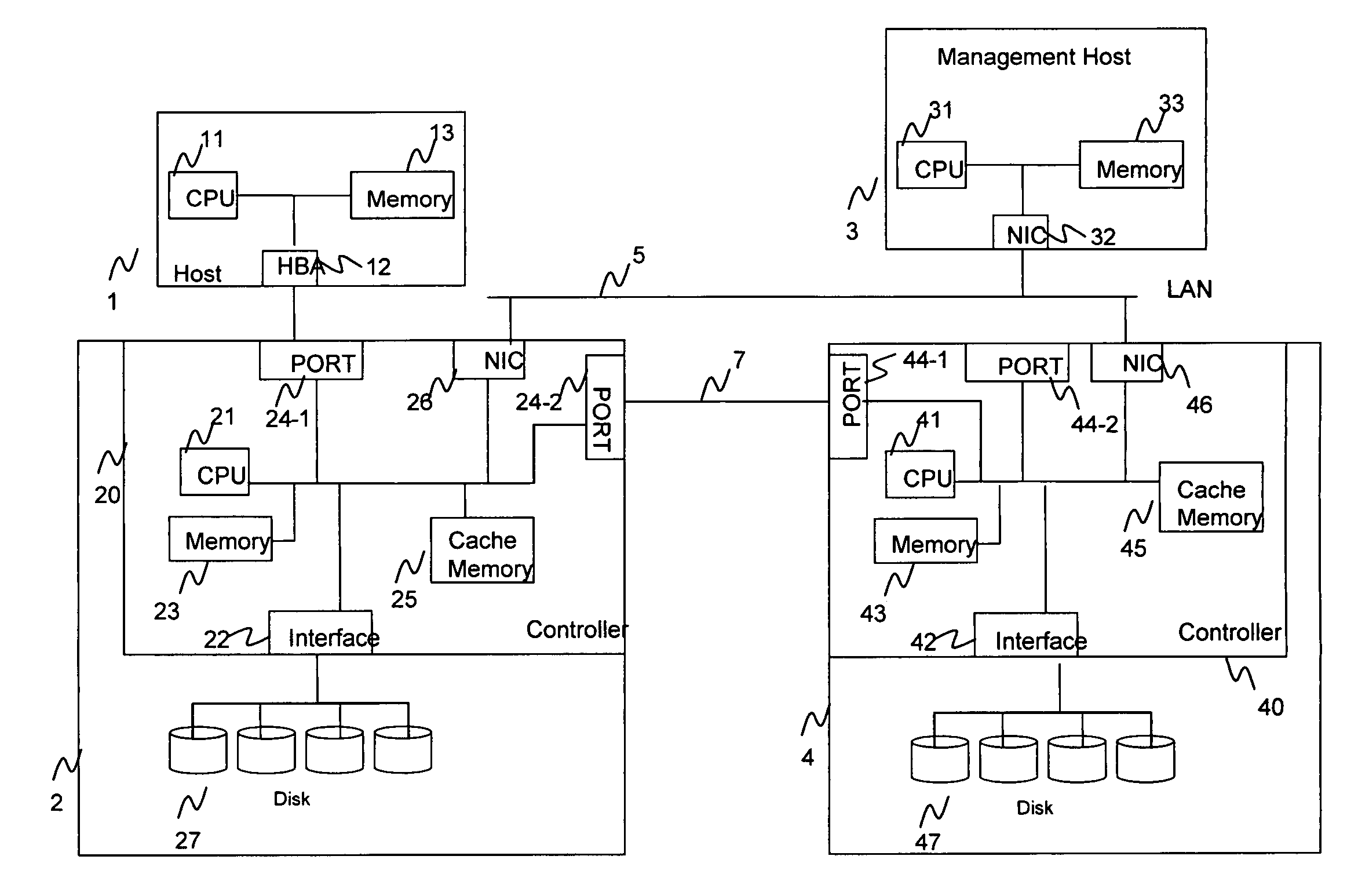
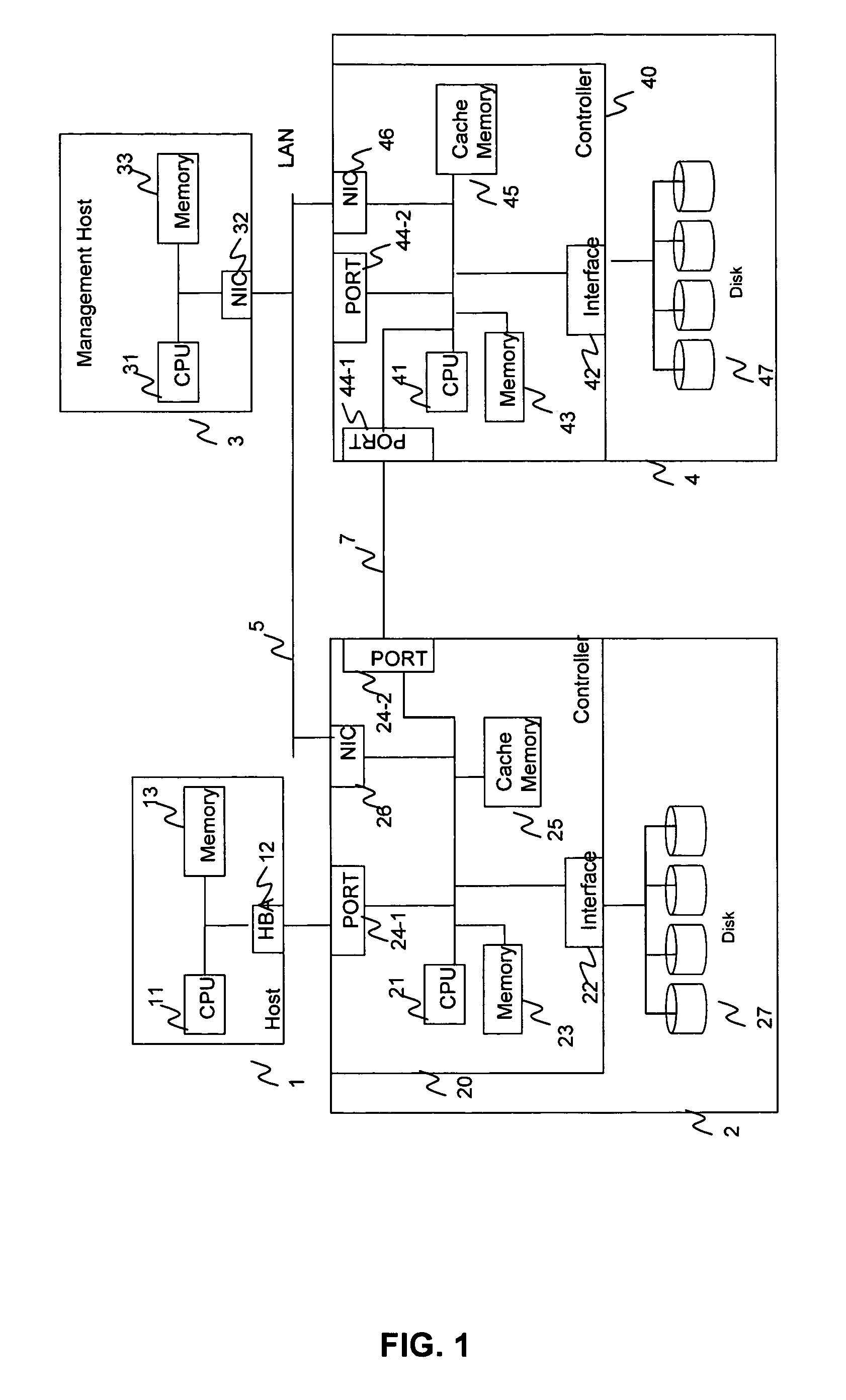
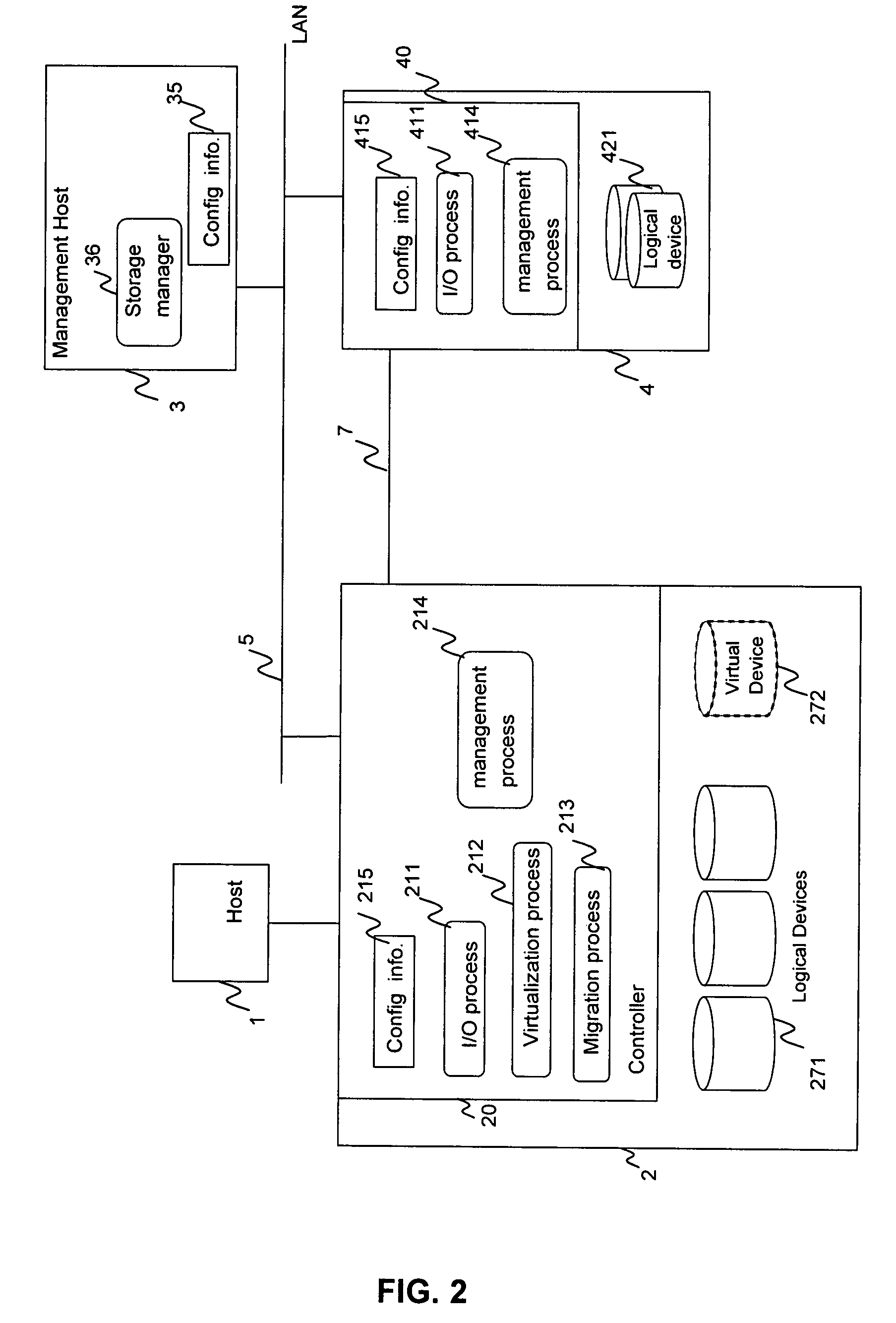
[0034]FIG. 1 and FIG. 2 show an example of an information system in which the method, apparatus and computer program of the present invention is applied. Particularly, FIG. 1 shows the physical components and FIG. 2 shows the logical components that are used in the present embodiment.

[0035]As illustrated in FIG. 1 a host 1 includes a Central Processing Unit (CPU) 11, a memory 13 and a Host Bus Adapter (HBA) 12. A primary storage 2 is provided that includes a disk controller 20 and a plurality of disks 27. Disk controller 20 includes a Central Processing Unit (CPU) 21, a backend interface 22, a memory 23, a plurality of ports 24-1 and 24-2, a cache memory 25, and a network interface card (NIC) 26. The ports 24-1 and 24-2 (generally called “ports 24”) may be used for connecting with HBA 12 of host computer 1 or an external storage 4. The ports 24 may be of the Fibre Channel, Ethernet, or other interface type. The number of ports 24 is not ...

3rd embodiment

3rd Embodiment

[0113]A. System Configuration

[0114]FIG. 19 shows a functional diagram of an information system of a 3rd embodiment of the present invention. The configuration of information system to which the 3rd embodiment is applied is almost the same as the information system of the 1st and 2nd embodiments as illustrated in FIG. 1 with the exception that the primary storage 2″ maintains cache devices and that write / update of data to the virtual volume is not transferred to the external device. Instead, the write / update of data is stored in the cache devices.

[0115]FIG. 19 illustrates the functions of the 3rd embodiment in the form of processes and a manager that reside in the primary storage 2″ and the external storage 4 and the management host 3. The processes include I / O process 211′, virtualization process 212, migration process 213 and management process 214 included in the controller 20 of the primary storage 2″, and I / O process 411 and management process 414 included in the c...


PUM


Abstract

An information system includes a primary storage system (PSS), a host, an external storage system (ESS), and a management host. The PSS uses virtual devices to treat logical devices in the ESS as if they were logical devices in the PSS. The ESS logical devices are configured using multiple disks for providing redundancy, such as in a RAID configuration, to enable migration of data following hardware failure in the ESS. When a disk forming part of an ESS logical device fails, the management host detects the failure and judges whether the ESS logical device is used by the PSS to form a virtual device. If the ESS logical device is used to form a virtual device, then the management host issues a migration request. In response to the migration request, the PSS migrates data from the ESS logical device to a logical device in the PSS to avoid data loss.

Description

BACKGROUND OF THE INVENTION[0001]The present invention relates generally to managing the availability of data in a storage system. More particularly the present invention relates to a method, apparatus and computer program for managing the availability of data in an external storage system such that the data remains in a highly available state even if a failure occurs in the external storage system.[0002]Storage virtualization is the software implementation that combines multiple network storage devices into what appears to be a single storage unit. Storage virtualization is used, for example, in a Storage Area Network (SAN) which is a high-speed sub-network of shared storage devices. The SAN makes tasks such as archiving, back-up, and recovery easier and faster. Examples of storage virtualization are provided by U.S. Pat. No. 6,721,841 and “TagmaStore Universal Storage Platform”, Hitachi Data Systems Corporation, December 2004[0003]U.S. Pat. No. 6,721,841 discloses a kind of virtua...

Claims


Application Information

Patent Timeline
Patent Type & Authority Patents(United States)
IPC IPC(8): G06F12/00
CPCG06F3/0605G06F3/0617G06F3/0664G06F3/067
Inventor KITAMURA, MANABU
Owner GOOGLE LLC
Why Eureka
Eureka Blog
Learn More