Cooling apparatus

a cooling device and cooling chamber technology, applied in lighting and heating apparatus, indirect heat exchangers, semiconductor/solid-state device details, etc., can solve the problems of inefficiency of local cooling fan, inability to efficiently conduct heat into the fin, and inability to efficiently conduct heat to the environment. to achieve the effect of improving heat transfer, increasing heat emission, and reducing the number of cooling fins

Inactive Publication Date: 2009-01-27
MINEBEA CO LTD
View PDF16 Cites 29 Cited by
  • Summary
  • Abstract
  • Description
  • Claims
  • Application Information

AI Technical Summary

Benefits of technology

[0007]The invention is based on the idea that, instead of using the stationary, heat-conducting surfaces of a cooling member to increase heat emission, a cooling member can be used which has moving surfaces like a fan wheel, and more particularly rotating surfaces. The cooling member can be designed in a similar way to a radial fan that has rotating, vane-like blades, or like an axial fan with substantially linear blades. The blades of the cooling member designed in the way of a fan take on the function of cooling fins, wherein it is possible to achieve substantially improved heat transfer from the surface of the cooling member to the cooling medium, particularly air, compared to the prior art. The invention further allows a greater degree of freedom in designing the actual cooling surfaces. The air flows generated by the cooling member can be optimized by the design of the fins or the blades of the cooling member in that, for example, a narrowing of the air flow channels generated by the blades is produced at the radially outer ends of the blades. It is a fundamental fact that the largest air acceleration and the strongest turbulence occurs in the region of the blades, which goes to optimize the transfer of heat.
[0008]In order to further improve the efficiency of the cooling apparatus according to the invention, an air guiding device to direct the air flow can be provided. In particular, this device can comprise a cover plate that separates an air suction side and an air release side. In a preferred embodiment of the invention, the cover plate coaxially encloses the shaft and has a central aperture so as to define a flow channel in the vicinity of the shaft. This flow channel ensures that the cooling air is drawn in an axial direction and emitted in a radial direction.
[0009]According to a further important aspect of the invention, the entire heat transport path from the heat source, i.e. the components to be cooled, to the cooling medium, such as air, is optimized. To this effect, the cooling structure comprises a container that is filled with a high heat-conducting medium. For its own part, this container is preferably made of a high heat-conducting material, such as copper or aluminum. In order to ensure the highest possible optimization of heat transportation from the surface area for introducing heat to the cooling member, the shaft preferably extends into the container and is fixedly connected to a rotating member within the container. It is then advantageous if the rotating member and the shaft are made of a high heat-conducting material, such as copper or aluminum, and connected to each other in a high heat-conducting manner. The rotating member serves to generate a flow and turbulence in the heat-conducting medium so as to optimize heat transfer from the container wall to the heat-conducting medium held in the container and from there via the rotating member and the shaft to the cooling member. The rotating member can be shaped like a disk. Transition resistance between the individual components is minimized. The rotation of the rotating member in the container goes to generate high heat transfer coefficients between the medium contained in the container and both the inner sides of the container as well as the surfaces of the rotating member. Heat is conducted along the shaft to the cooling member.
[0010]In a preferred embodiment of the invention, the shaft is made of a high heat-conducting material having a large cross-section. In another embodiment, the shaft is designed as a heat pipe that can achieve very high axial heat transportation.

Problems solved by technology

The efficiency of a fan used to locally increase the air flow speed in the region of the cooling member is always subject to restrictions due to the fact that the separation of heat-exchange surfaces and the generation of air flows constantly involves a compromise between air flow and heat conductivity.
The emission of heat to the environment requires the largest possible surface area, which, given limited space, can only be realized by using a large number of cooling fins.
If the cooling fins are too thin, heat cannot be efficiently conducted into the fins, i.e. a minimum fin thickness, which has to be made to adapt to the overall system, is necessary.
If the outside dimensions of the cooling member are limited, this goes to greatly reduce the free cross-section available for the cooling channels.
This results in a substantial rise in the temperature of the cooling medium and thus the temperature of the components to be cooled as well, i.e. the cooling effect declines considerably.

Method used


Image

  • Cooling apparatus
  • Cooling apparatus

Examples


Embodiment Construction

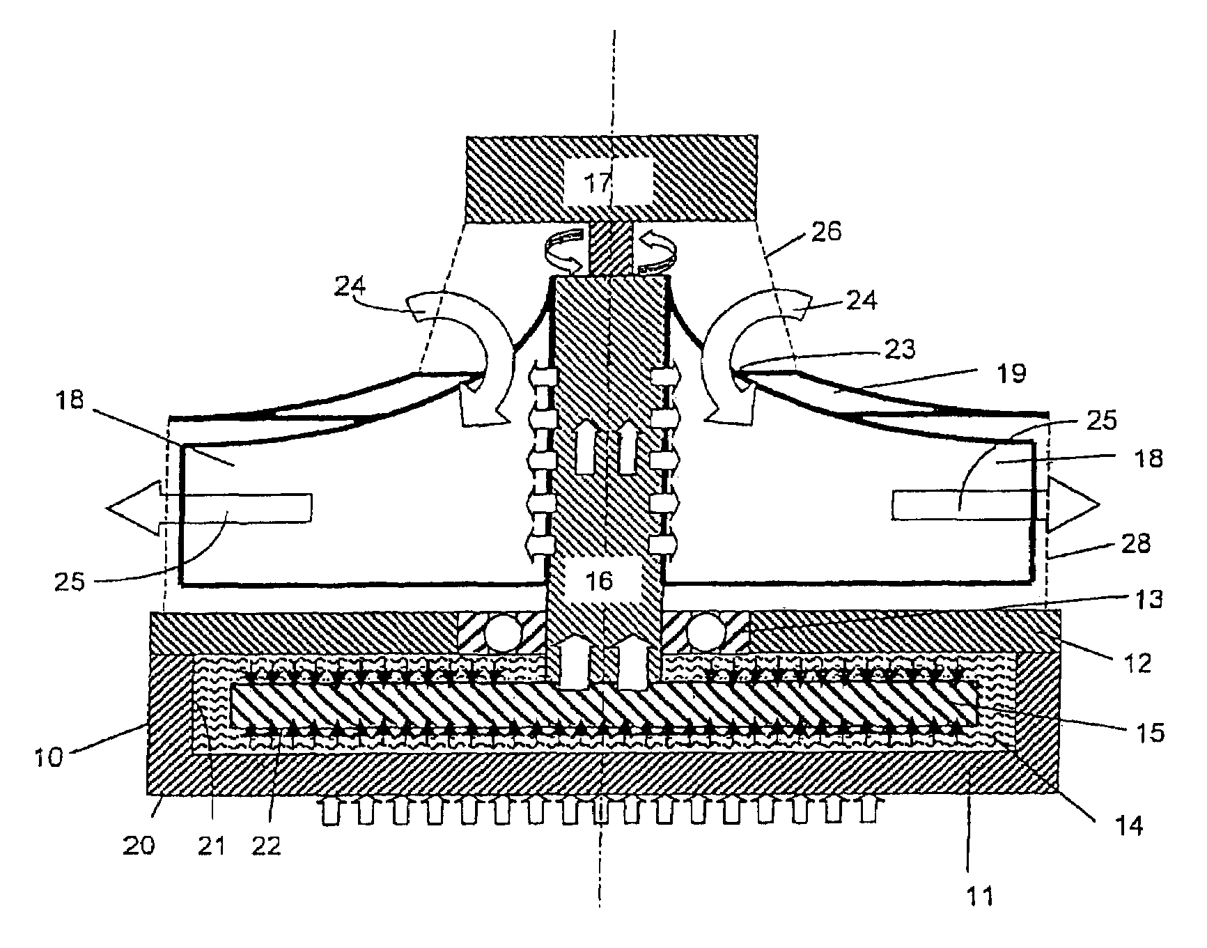
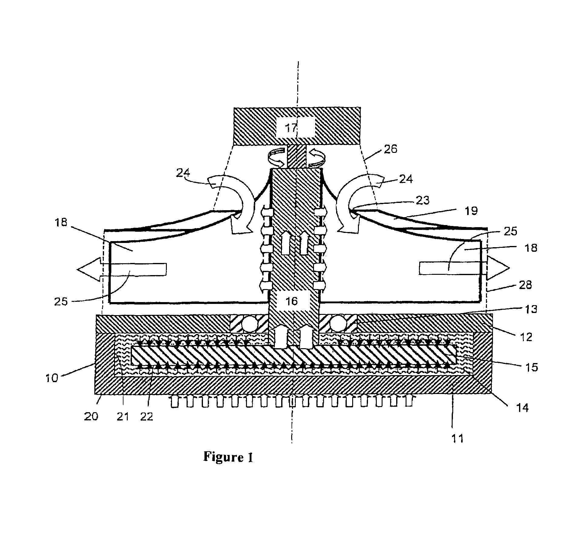
[0014]The FIGURE shows a cooling structure 10 taking the form of a closed container that comprises a baseplate 11 and a cover 12. A cylindrical cavity is formed in the baseplate 11 that is tightly sealed by the cover 12. Suitable materials for the baseplate 11 and the cover 12 include high heat-conducting materials such as aluminum or copper. A heat-conducting medium 14, particularly a liquid medium, is enclosed in the container 10, the container being fully filled with this medium 14. Apertures (not illustrated) that can be hermetically sealed may be provided in the cover 12 and / or the baseplate 11 for purposes of filling the container 10.

[0015]A shaft 16 is rotatably supported in the container cover 12 by means of a roller bearing 13, particularly a ball bearing. Instead of a roller bearing, a sliding bearing, particularly a fluid bearing or a hydrodynamic bearing, can be provided. The shaft 16 extends into the interior of the container 10 and is fixedly connected to a rotating me...


PUM


Abstract

The invention relates to a cooling apparatus having a cooling structure that comprises at least one surface area for introducing heat, and a cooling member that is connected to the cooling structure in a heat-conducting manner, wherein the cooling member is moveable so as to generate an air flow by means of the movement of the cooling member, the air flow supporting heat emission from the cooling member to the environment.

Description

FIELD OF THE INVENTION[0001]The invention relates to a cooling apparatus comprising a cooling structure that is provided with at least one surface area for introducing heat, and a cooling member which is connected to the cooling structure in a heat-conducting manner.BACKGROUND OF THE INVENTION[0002]In the prior art, cooling members are used to cool electronic components such as microprocessors or the power IC components of data processing equipment that comprise a plurality of fins so as to provide the largest possible surface area for the heat exchange between the cooling member and the cooling medium, such as air, surrounding the cooling member. To achieve efficient cooling, the thermal resistance between the surface of the components to be cooled, the cooling member and the cooling medium should be minimized. Where only small quantities of heat need be dissipated, a high heat-conducting connection between the components to be cooled and the cooling member is sufficient to provide...

Claims


Application Information

Patent Timeline
Patent Type & Authority Patents(United States)
IPC IPC(8): F28F7/00F28D15/00H05K7/20F28F13/12H01L23/467H01L23/473
CPCF28F13/125H01L23/467H01L23/473H01L2924/0002H01L2924/00
Inventor BREIER, ANTONKAMAGATA, HIDETOSHI
Owner MINEBEA CO LTD
Why Eureka
Try Eureka