Power cable assembly connector

a technology of power cable and connector, which is applied in the direction of connection, contact member material, electrode supporting device, etc., can solve the problems of affecting the operation of the power cable, and unable to allow relative movement, etc., and achieves the effect of avoiding bending resistance, avoiding bending resistance, and avoiding bending resistan

Active Publication Date: 2009-01-27
REHRIG RICHARD B
View PDF3 Cites 16 Cited by
  • Summary
  • Abstract
  • Description
  • Claims
  • Application Information

AI Technical Summary

Benefits of technology

[0004]Briefly, the present invention comprises a coupling particularly adapted for connecting an air cooled TIG welding torch to the power cable assembly so as to provide both a gas-tight connection between the torch body and the outer hose of the assembly and a positive electrical connection between the torch body and the power cable in the assembly while allowing the outer hose of the power cable assembly to undergo rotational movement with respect to the torch as the torch handle is twisted and turned during a welding procedure. In a preferred embodiment, the connector assembly of the present invention comprises an electrically conductive tubular member adapted to be affixed to the extended end of the power cable in a welding torch power cable assembly and define both an electrical connection and a gas passageway between the power cable assembly and the torch body. A hose attachment sleeve is mounted on and extends about at least a portion of the electrically conductive tubular member so as to form a gas-tight seal therewith while allowing relative rotational movement of the sleeve and tubular member. A threaded connector is carried by the downstream end of the tubular member for rigid securement to the torch body while providing shielding gas flow therethrough to the torch head. The hose attachment sleeve is configured to be secured to the downstream end of the outer power cable assembly hose whereby the hose can undergo rotational movement with the sleeve about and with respect to the power cable and the tubular member affixed to the cable such that torsional resistance of the outer hose to rotation of the welding torch during a welding procedure is substantially eliminated.

Problems solved by technology

The connection of the power cable to the torch body is firm and does not allow for relative movement therebetween.
As a result, torsional resistance is encountered when the user manipulates the torch body during welding procedures.
The procedure is tedious, precise and requires complete control of the torch movement by the welder.
Overcoming the resistance to such movement created by the outer hose of the power cable assembly during the procedure can be very tiring to the welder.

Method used


Image

  • Power cable assembly connector
  • Power cable assembly connector
  • Power cable assembly connector

Examples


Embodiment Construction

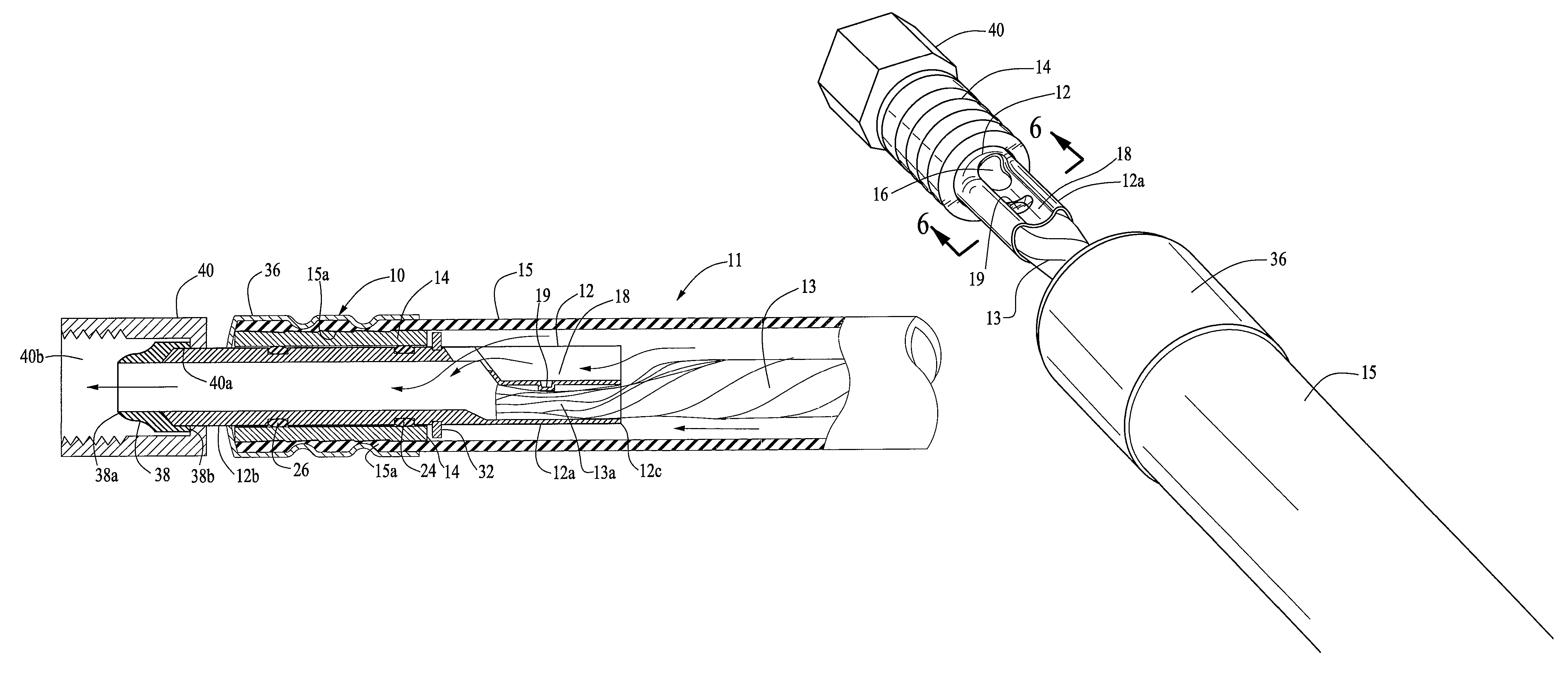
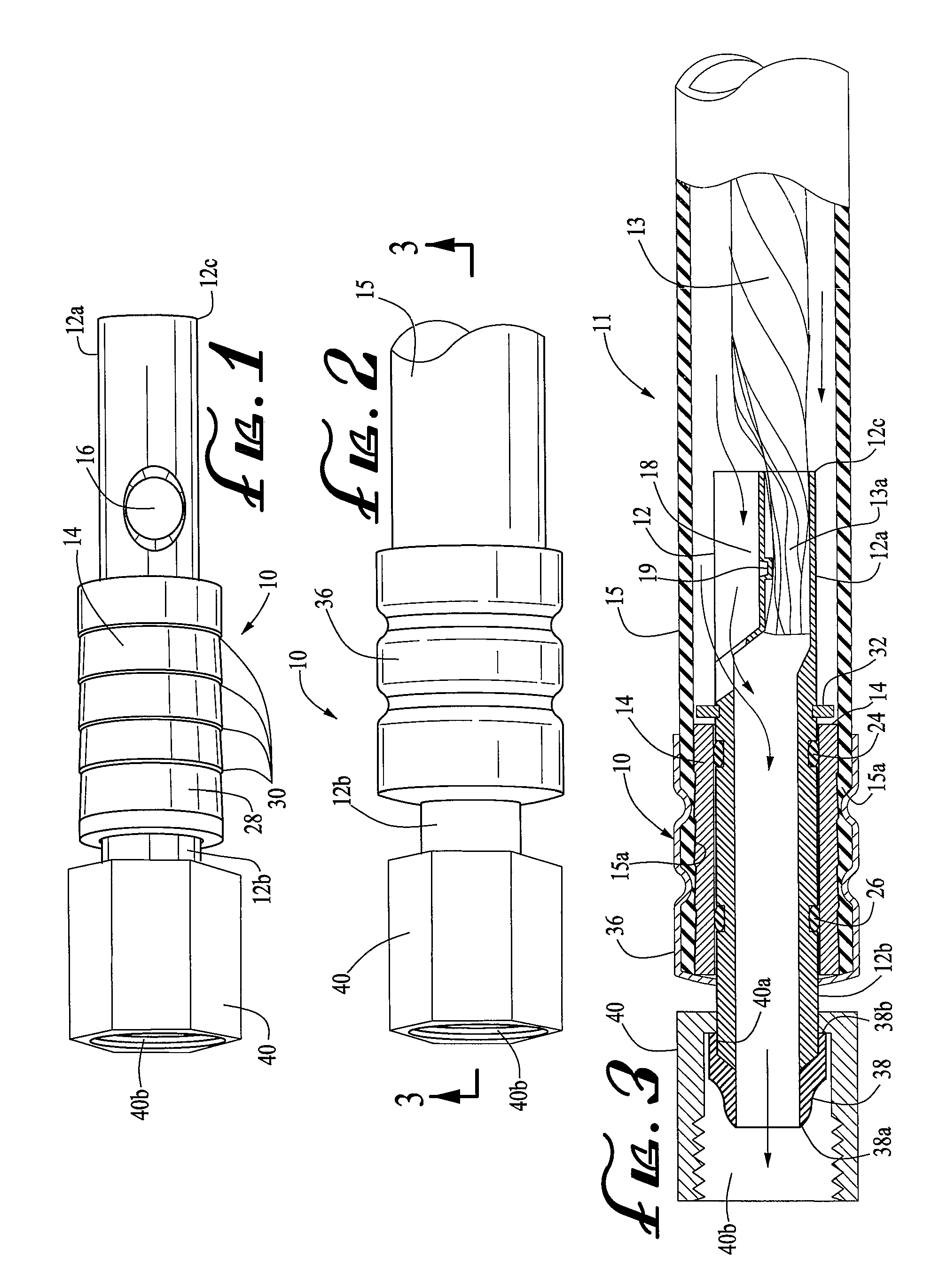
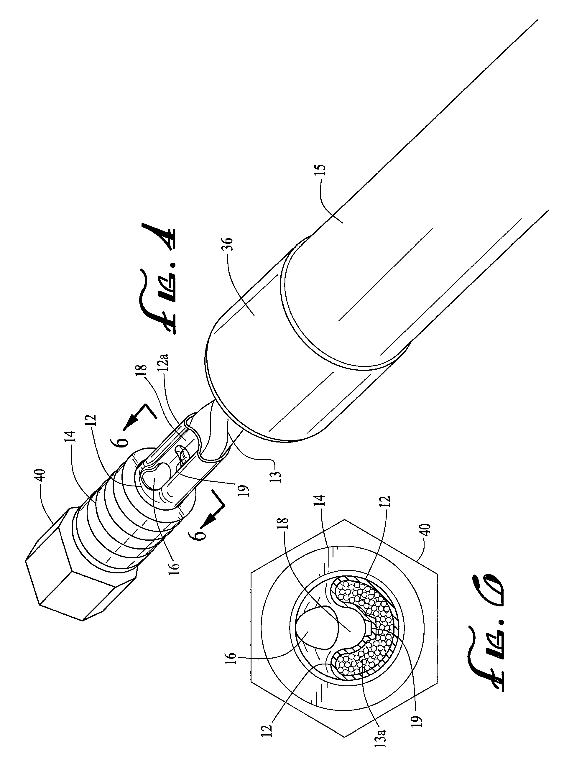
[0012]Referring now in detail to the drawings, a preferred embodiment of the connector assembly 10 of the present invention is shown that is particularly configured to releasably secure a power cable assembly 11 to a TIG welding torch (not shown). The connector assembly 10 comprises a tubular member 12 formed of an electrically conductive material, preferably copper, for electrically coupling the welding torch with the power cable 13 within the power cable assembly 11 and providing a flow passage for the shielding gas from the power cable assembly to the torch. The connector assembly 10 also includes a hose attachment sleeve 14, preferably constructed of a rigid, heat resistant material, such as brass, for securing the connector assembly 10 to the extended end portion 15a of the outer hose 15 in the power cable assembly. The tubular member 12 is preferably of single-piece construction and defines a first upstream portion 12a and a second downstream portion 12b. The first portion 12a...


PUM


Abstract

A connector assembly for releasably securing a welding torch to an extended end portion of a power cable assembly having an outer hose disposed about an electrically conductive cable for directing gas therethrough to the torch. An aperture is provided in the side wall of an electrically conductive tubular member between upstream and downstream portions thereof. An upstream portion of the tubular member is crimped about an end of the cable so as to define a generally U-shaped trough extending along the upstream portion of the tubular member, creating a gas flow path extending therealong to and through the aperture, into and through the downstream portion of the tubular member. A hose attachment sleeve is rotatably and sealably mounted on a pair of axially spaced sealing members on the downstream portion of the tubular member so that the torch can be rotated with respect to the hose during use, reducing strain on the welder.

Description

BACKGROUND OF THE INVENTION[0001]The present invention relates to power cable assembly connectors and more particularly, to a connector for releasably securing a power cable assembly to a TIG welding torch that enables a power cable assembly hose to twist or turn with respect to the torch during use to reduce the strain on the welder.[0002]Welding torches used in TIG welding (tungsten inert gas), also known as GTAW (gas tungsten arc welding) are two general types, air or gas cooled and water cooled. Air or gas cooled welding torches are generally employed in lighter duty applications and are cooled by dissipating to the surrounding air the heat buildup in the torch during the weld cycle. Air cooled torches are commonly used for welding on job sites as they do not require cooling lines and water circulating equipment associates with the higher capacity water cooled torches. The power cable assembly used on such air cooled torches typically comprises an outer flexible plastic or rubbe...

Claims


Application Information

Patent Timeline
Patent Type & Authority Patents(United States)
IPC IPC(8): H01R4/60
CPCB23K9/287H01R4/60H01R4/183H01R13/005
Inventor REHRIG, RICHARD B.
Owner REHRIG RICHARD B
Why Eureka
Try Eureka