Recovering a non-linear warping function from images

a non-linear warping function and image technology, applied in the field of image processing, can solve the problems of computational demands of existing non-linear warping recovery methods, and the method is limited to linear distortion along a single direction

Inactive Publication Date: 2009-01-27
MITSUBISHI ELECTRIC RES LAB INC
View PDF20 Cites 6 Cited by
  • Summary
  • Abstract
  • Description
  • Claims
  • Application Information

AI Technical Summary

Problems solved by technology

However, that method is limited to linear distortions along a single direction.
Existing non-linear warping recovery methods are computationally demanding because those methods include a 2-D minimization problem, see, e.g., Levin et al., “Dynamic planar warping for optical character recognition,” Proceedings of ICASSP, pp.

Method used


Image

  • Recovering a non-linear warping function from images
  • Recovering a non-linear warping function from images
  • Recovering a non-linear warping function from images

Examples


Embodiment Construction

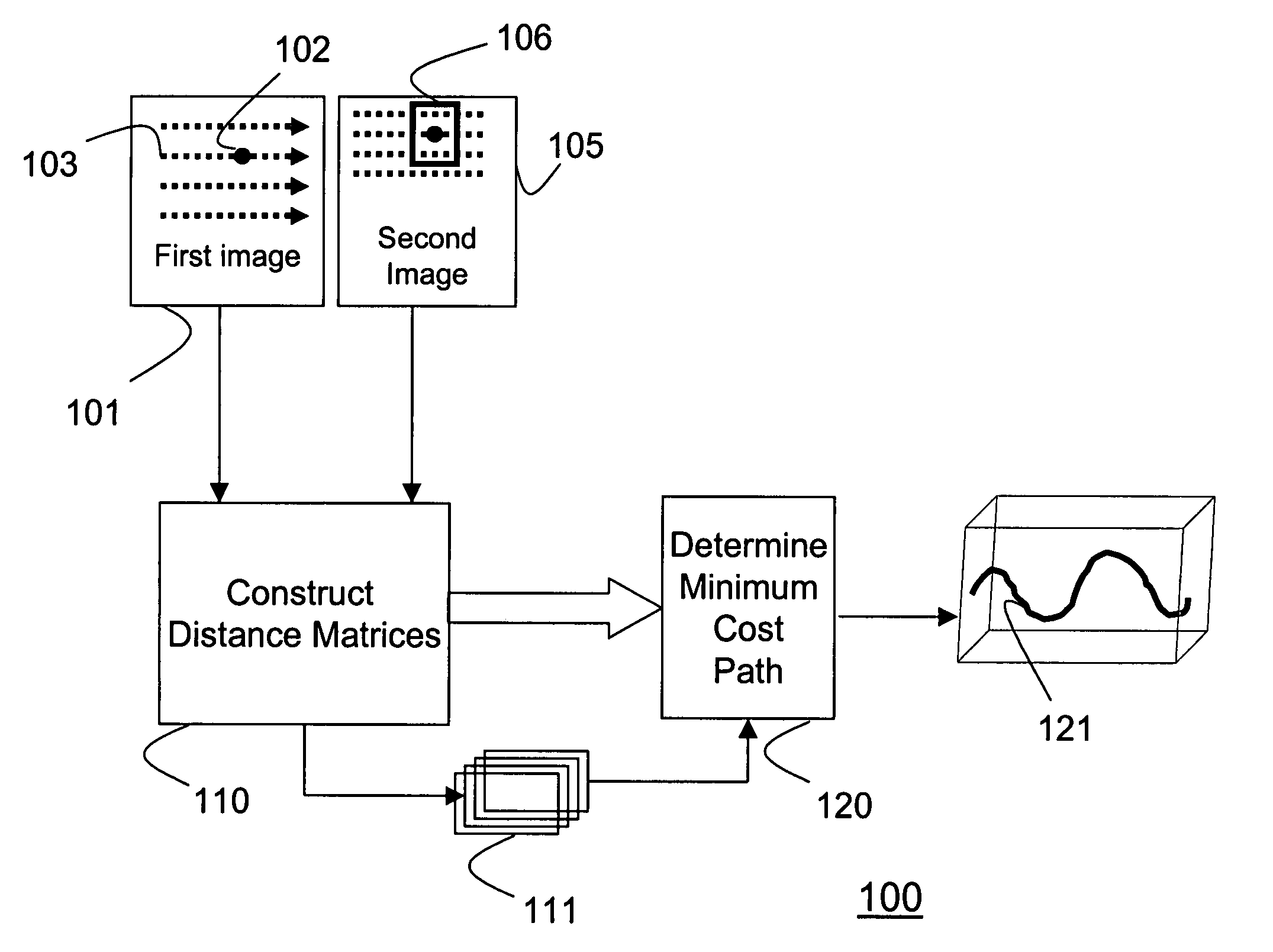
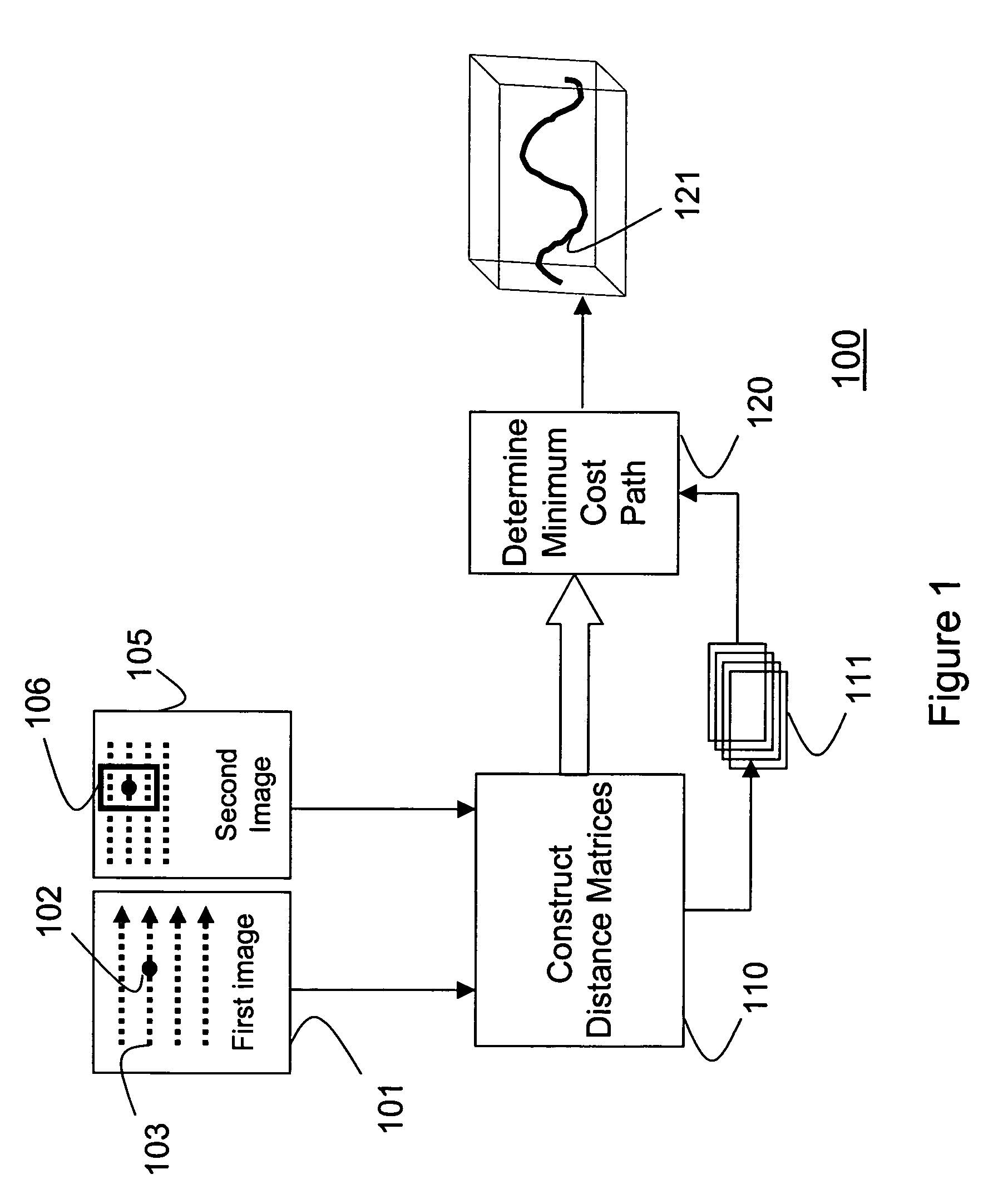
[0012]As shown in FIG. 1, a method 100 for recovering a warping function according to my invention takes as input a first image 101 and a second image 105. A distance matrix 111 is constructed 110 for each pixel 102 in each scan-line 103 of the first image. Each distance matrix 111 represents distances between the pixel 102 and a block of corresponding pixels 106 of the second image. The distances measure how far the pixel 102 in the first image is displaced in the second image. A center of the block of pixels in the second image corresponds to a location of the pixel 102 in the first image. The matrices 111 are produced according to an order of the scan-line. A minimum cost path 121 is determined 120 through the ordered distance matrices 111. The minimum cost paths for all scan lines represent a warping function between the first image and the second image.
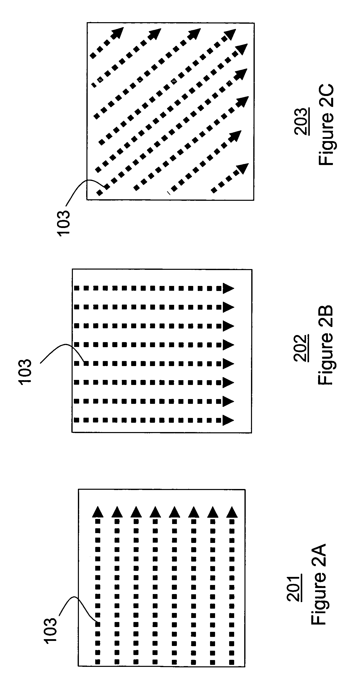
[0013]Scan-Line

[0014]As shown in FIGS. 2A-2C, the scan-line 103 is a 1-D line in the first image 101. The scan-line can be a ho...


PUM


Abstract

A method determines a warping function between a first image and a second image. For each pixel in each scan-line of the first image, a distance matrix is constructed which represents distances between the pixel and a plurality of corresponding pixels of a second image. The distance matrices are ordered according a scan-line order of the pixels. A minimum cost path through the ordered distance matrices represents the warping function between the first image and the second images

Description

FIELD OF THE INVENTION[0001]The present invention relates generally to the field of image processing, and more particularity to recovering a warping function between images.BACKGROUND OF THE INVENTION[0002]Determining a warping function between two images is important for several applications. For instance, many projector systems require automatic recovery of the shape of a display surface. There, a known pattern is projected onto a surface having an unknown shape. An image of the pattern on the surface is compared with the known pattern to find the warping function, which manifests the shape of the surface. The warping function minimizes an error between the original and projected images.[0003]Another application is to correct optical distortion of a camera. Distortion can be due to lens distortions, water drops on the lens, distorting glass in front of the lens, or atmospheric conditions.[0004]A number of methods are known for recovering warping functions between images, see, e.g....

Claims


Application Information

Patent Timeline
Patent Type & Authority Patents(United States)
IPC IPC(8): G06K9/62G06F15/00G06K9/36G06K9/68H04N1/60G06K9/48
CPCG06K9/50G06K9/6206G06T3/0093G06T5/006G06V10/421G06V10/754
Inventor PORIKLI, FATIH M.
Owner MITSUBISHI ELECTRIC RES LAB INC
Why Eureka
Try Eureka