Supercharge Your Innovation With Domain-Expert AI Agents!

Premasher

a pre-masher and mash technology, applied in the field of pre-mashers, can solve the problems of sticky residues that cannot be removed with great effort, and the formation of intensive dust formation, and achieve the effect of increasing the speed of mash water and increasing the speed

Inactive Publication Date: 2009-02-03
ANTON STEINECKER MASCHINENFABRICK GMBH
View PDF13 Cites 0 Cited by
  • Summary
  • Abstract
  • Description
  • Claims
  • Application Information

AI Technical Summary

Benefits of technology

[0008]Turbulences are preferably produced by a tangential component of the mash water. In this way, a certain rotational flow is superimposed on the radial flow, with the rotational flow causing in a particularly effective manner higher relative speeds between the grist and the mash water, whereby the mixing degree is markedly increased and the dust particles are bound immediately.
[0011]Another measure is seen in that the inlet opening for the mash water is implemented as a nozzle in such a way that the speed of the mash water is increased above an average speed.

Problems solved by technology

In addition, there is the problem of very intensive dust formation, primarily in cases where grist and water are fed into the mash tub via a downpipe.
The fine dust rising in the course of this process adheres to structural components and, together with water vapour, it forms sticky residues that can only be removed with great effort, especially in cases in which a so-called powder grist containing an extremely high percentage of powder is used, this type of grist being obtained e.g. from a hammer mill.
However, it turned out that not even the use of this premasher resulted in an optimum mixing degree between water and grist, since the grist was enveloped by a kind of water veil and since this had effect that the grist and the water were not thoroughly mixed.

Method used


Image

  • Premasher
  • Premasher
  • Premasher

Examples


Embodiment Construction

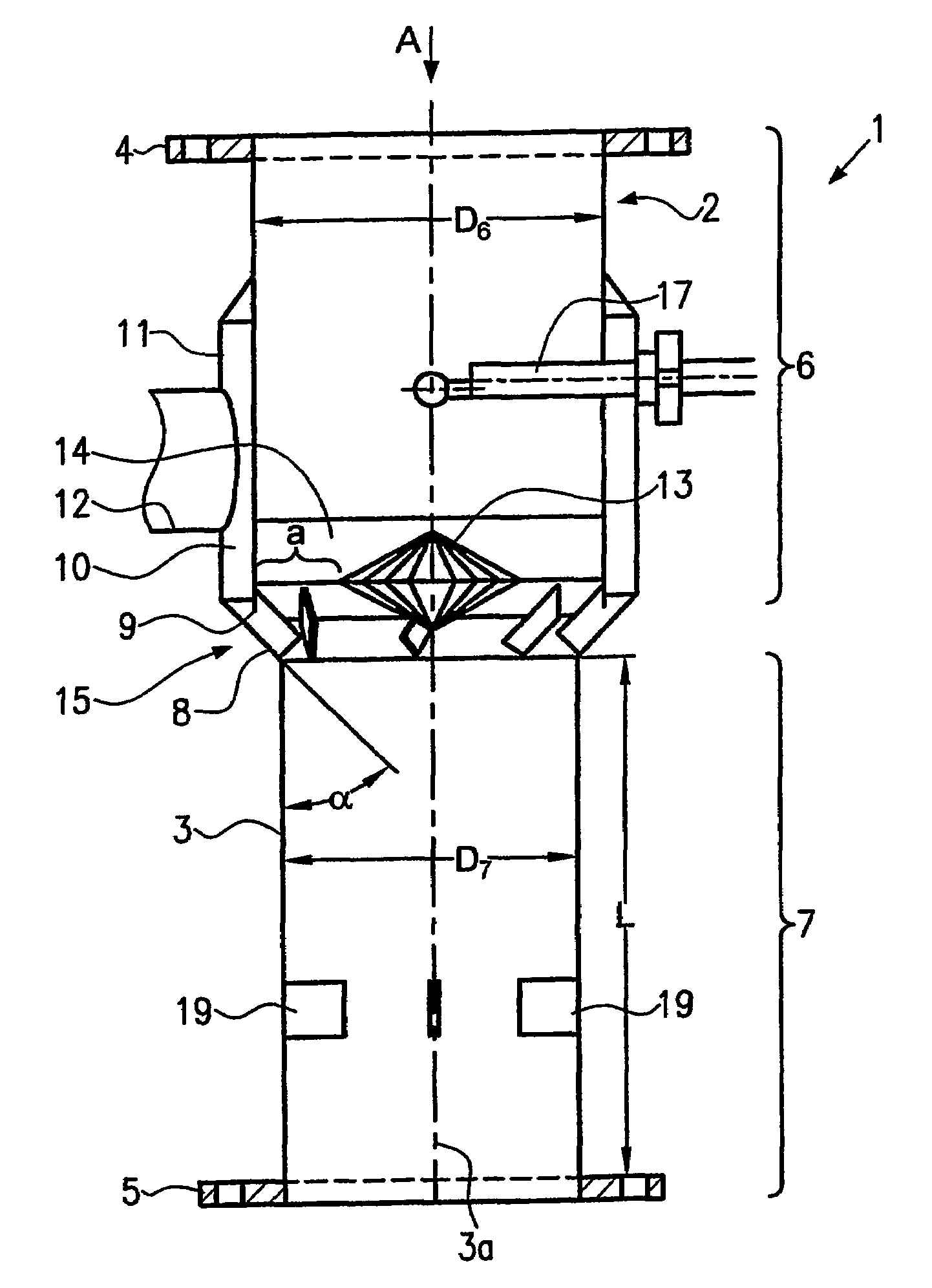
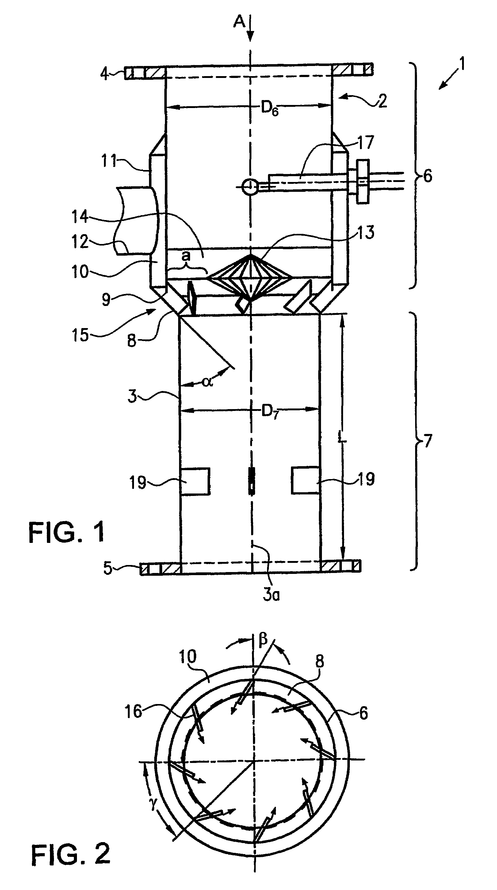
[0020]FIG. 1 to 3 show a first embodiment of a premasher 1 according to the present invention, comprising a downpipe designated generally by reference numeral 2; the wall 3 of said downpipe 2 is arranged such that its axis 3a extends perpendicular and it is adapted to be connected via a first fastening flange 4 to the discharge pipe of a grist container, a delivery line or the like, and via a second flange 5 to a mash tub in such a way that the grist will fall through the downpipe 2 in a vertical, gravity-conditioned flow A.

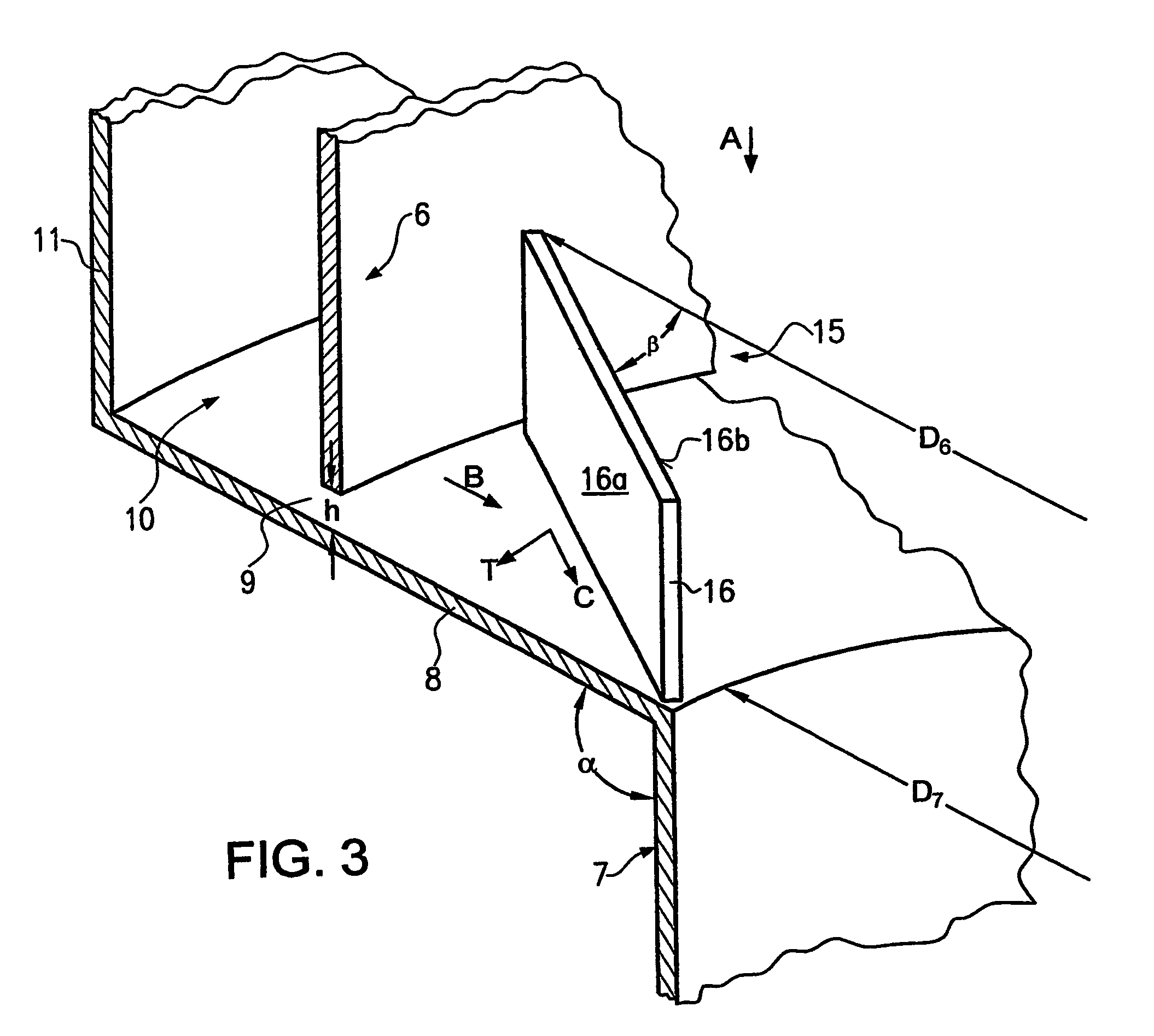
[0021]The wall 3 of the downpipe 2 comprises an area 6 having a first internal width D6 and defining an upper area when seen in the flow direction A and an area 7 having an internal width D7 and defining a lower area when seen in the flow direction A. D6 is larger than D7 and merges with D7 via a transition surface 8. The transition surface 8 extends obliquely towards the center line 3a at an angle α relative to the flow direction A. The angle α is an angle of ap...


PUM

PropertyMeasurementUnit
speedaaaaaaaaaa
widthaaaaaaaaaa
speedaaaaaaaaaa

Abstract

A premasher (1, 100) for beer brewing processes, having a downpipe (2) for a stream of grist and an inlet opening (9) for mash water which opens into the downpipe (2). In order to improve the mixing degree of mash water and grist, the inlet opening (9) has associated therewith a turbulence-generating flow guide means (15, 25).

Description

REFERENCE TO RELATED APPLICATIONS[0001]This disclosure claims the benefit of the filing date of International Application No. PCT / EP02 / 14173, having an international filing date of Dec. 12, 2002, which designated the United States of America, and this disclosure is the United States national stage of that international application. This disclosure further claims priority to European patent application EP 02001698.6, filed Jan. 24, 2002.[0002]1. Field of the Invention[0003]The invention relates to premasher used for beer brewing.[0004]2. Background of the Invention[0005]In beer brewing processes, the rough-ground malt must be mixed with water, i.e. mashed, so as to convert insoluble substances, such as in particular starch, into soluble substances, in particular sugar. For obtaining a good yield and in order to allow unproblematic further processing, it must be guaranteed that the grist is mixed completely with water and that the formation of clots is prevented. In addition, there is...

Claims


Application Information

Patent Timeline
Patent Type & Authority Patents(United States)
IPC IPC(8): C12C11/00C12C7/04C12C13/00
CPCC12C7/04C12C7/042
Inventor KAMMERLOHER, HELMUT
Owner ANTON STEINECKER MASCHINENFABRICK GMBH
Features
  • R&D
  • Intellectual Property
  • Life Sciences
  • Materials
  • Tech Scout
  • Unparalleled Data Quality
  • Higher Quality Content
  • 60% Fewer Hallucinations
Learn More