
Firearm ammunition projectile

a projectile and ammunition technology, applied in the field of ammunition projectiles, can solve the problems of generating considerable pollution in firing ranges, affecting the accuracy of projectiles, and kinetic energy dissipation very slowly, and achieve the effect of precise and reliable trajectory

Inactive Publication Date: 2009-02-03
ETAT FR REPRESENTE PAR LE DELEGUE GENERAL POUR LARMEMENT
View PDF27 Cites 22 Cited by
  • Summary
  • Abstract
  • Description
  • Claims
  • Application Information

AI Technical Summary

Benefits of technology

[0008]The aim of the present invention is to overcome these disadvantages by proposing a projectile for a firearm with a precise, reliable trajectory, with limited penetration in a soft medium, and which, depending upon the manner of manufacture, is capable of either passing through or being stopped by a bullet-proof vest.

Problems solved by technology

For the most part, they are lead-based, causing them to generate considerable pollution in firing ranges during training and competitions.
Additionally, when used outdoors, their kinetic energy dissipates very slowly.
For this reason, when used in public, they are capable of passing through two people, one after the other, making them especially dangerous.
Because of this they are incompatible with use by police forces.
This shell does not ensure a precise trajectory and cannot be adapted to handguns.
Therefore it does not offer a satisfactory solution.
Thus, once the projectile has traveled for a certain distance, for example 300 meters for hunting weapon projectiles, the helicoidal grooves slow rotation on the trajectory, making it unstable and causing it to tilt down toward the ground.
Therefore, this solution is not satisfactory.
Therefore, this is not a satisfactory solution.
Thus, this solution is unsatisfactory.

Method used


Image

  • Firearm ammunition projectile
  • Firearm ammunition projectile
  • Firearm ammunition projectile

Examples


Embodiment Construction

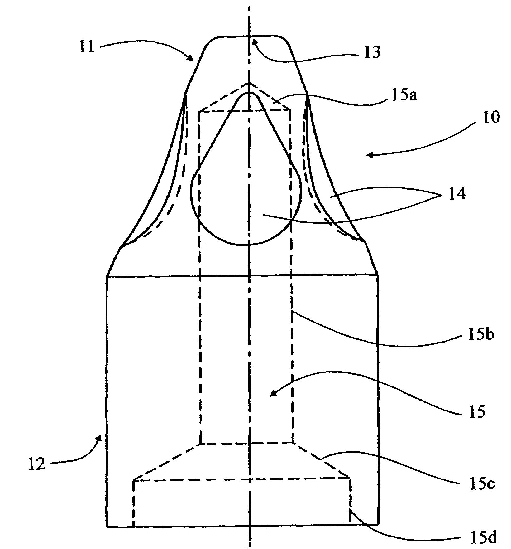
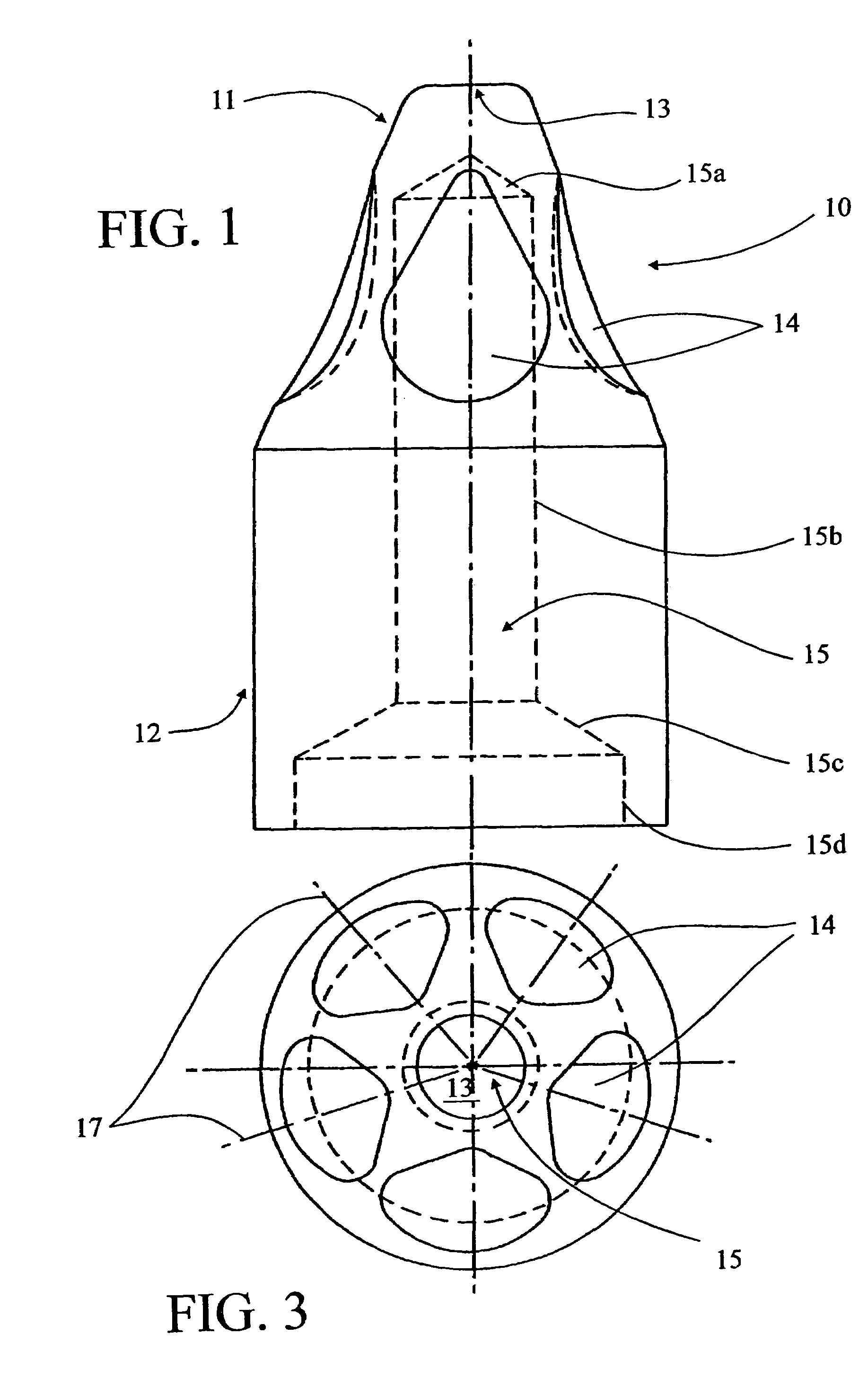
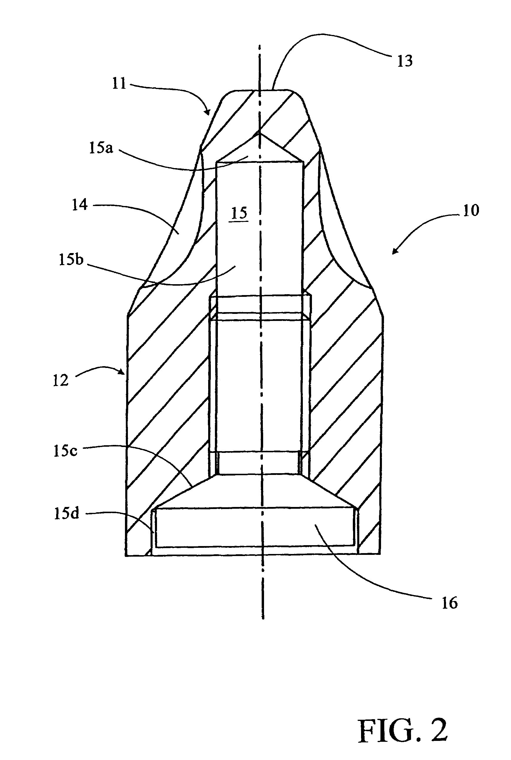
[0026]The projectile according to the invention illustrated by FIGS. 1 through 3 is designed principally for use by public security services. One of its essential features is that it can be stopped by a bulletproof vest, specifically a bulletproof vest consisting of 24 layers of sheets of synthetic material such as, for example, the commercial brand KEVLAR™ or any equivalent material with similar characteristics.

[0027]As shown in FIGS. 1 through 3, projectile 10 comprises an approximately conical nose 11 and a cylindrical cap 12. Conical nose 11 has an angle at the tip ranging from 30 to 45° and preferably equal to approximately 38°. It is provided with a central flat portion 13 that may be larger or smaller and which is essentially circular in shape, with a diameter ranging from 10 to 50% of the diameter of the projectile at the base of nose 11 or cap 12. Preferably, the diameter of flat area 13 essentially ranges from one-fourth to one-third of the diameter of projectile 10. On it...


PUM


Abstract

An ammunition projectile for a firearm comprising a projectile having a nose and a cap which is designed to slow down sufficiently, when traveling through air so as to be stopped by a bulletproof vest while the projectile still has a precise and reliable trajectory. The projectile (10) has a generally truncated nose (11) and a cylindrical cap (12). The nose (11) is provided with a central, essentially circular flat section (13) which can be made larger or smaller and which has a diameter of between 10 and 50% of the diameter of the projectile at the base of the nose (11) or the cap (12). The lateral face of the truncated nose (11) is provided with five indentations (14) which are disposed symmetrically in relation to axial planes and which are obtained by one of stamping, milling, or some other suitable machining method.

Description

[0001]This application is a national stage completion of PCT / FR2003 / 003036 filed Oct. 15, 2003 which claims priority from French Application Serial No. 02 / 12922 filed Oct. 17, 2002.FIELD OF THE INVENTION[0002]The present invention concerns an ammunition projectile for a firearm, particularly a handgun, said projectile comprising a nose and a cap.BACKGROUND OF THE INVENTION[0003]Projectiles known in the prior art have various disadvantages. For the most part, they are lead-based, causing them to generate considerable pollution in firing ranges during training and competitions. Additionally, when used outdoors, their kinetic energy dissipates very slowly. For this reason, when used in public, they are capable of passing through two people, one after the other, making them especially dangerous. Because of this they are incompatible with use by police forces.[0004]Publication FR-A-2 517 764 describes a training shell used for shooting training and regulating artillery pieces. This train...

Claims


Application Information

Patent Timeline
Patent Type & Authority Patents(United States)
IPC IPC(8): F42B10/22F42B10/24F42B10/52
CPCF42B10/22F42B10/52
Inventor FICHOT, CHRISTOPHEDELOUME, PIERREDORRZAPF, JEAN-JACQUES
Owner ETAT FR REPRESENTE PAR LE DELEGUE GENERAL POUR LARMEMENT
Learn More