Thermal barrier coating with a plasma spray top layer

a technology of plasma spray and top layer, which is applied in the direction of superimposed coating process, coating, natural mineral layered products, etc., can solve the problem of degrading of desert airfoils of turbine engines

Active Publication Date: 2011-01-25
RTX CORP
View PDF29 Cites 12 Cited by
  • Summary
  • Abstract
  • Description
  • Claims
  • Application Information

AI Technical Summary

Benefits of technology

[0007]In accordance with the present invention, there is provided a turbine engine component which broadly comprises a substrate, a thermal barrier coating deposited onto the substrate, and means for sealing an outer surface of the thermal barrier coating and thereby limiting molten sand penetration into the thermal barrier coating.

Problems solved by technology

Turbine engine airfoils used in desert environments may degrade due to sand related distress of thermal barrier coatings.

Method used


Image

  • Thermal barrier coating with a plasma spray top layer
  • Thermal barrier coating with a plasma spray top layer

Examples


Embodiment Construction

)

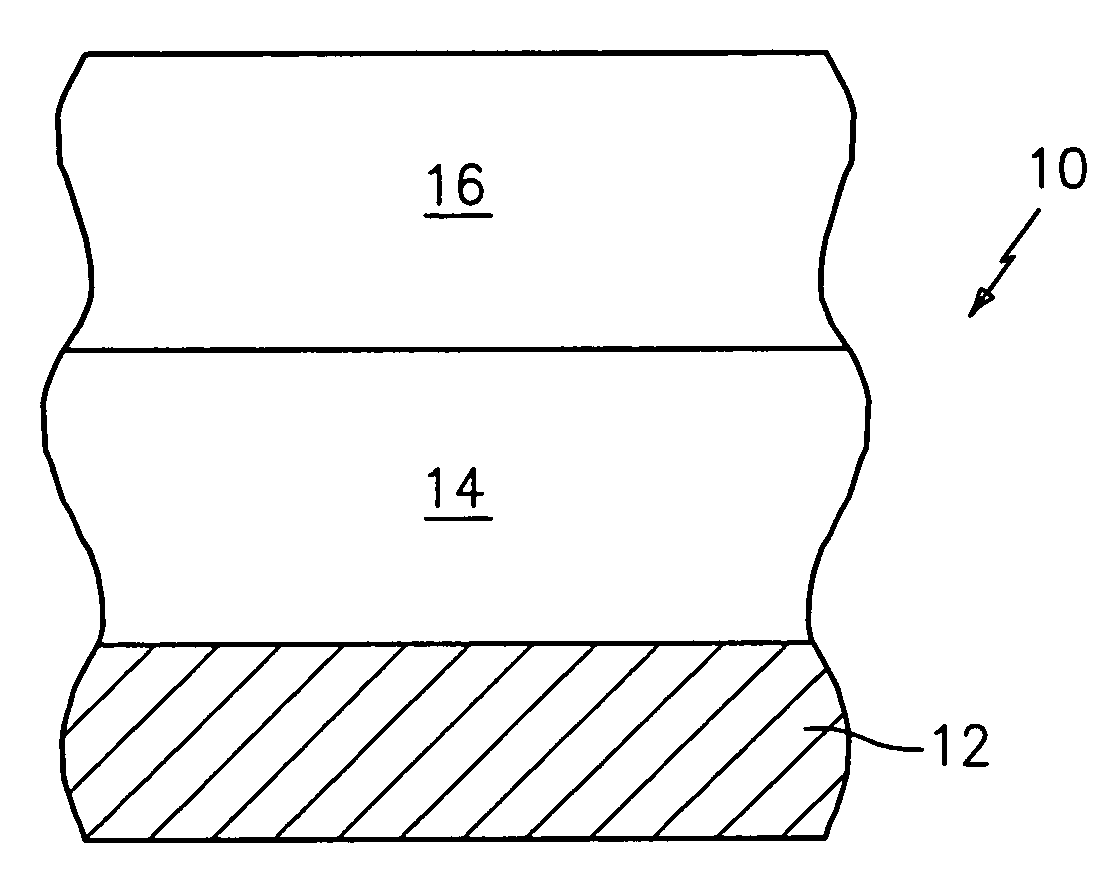
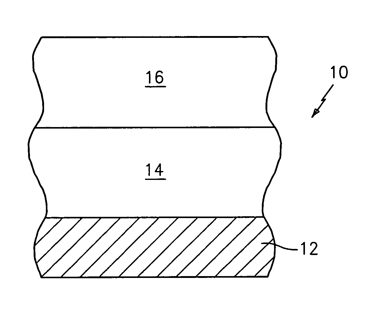
[0011]Referring now to the FIGURE, there is shown a turbine engine component 10, such as a blade, a vane, a combustor panel, or a seal having a substrate 12, such as an airfoil portion or a platform portion of a blade or vane or a portion of a combustor panel or a portion of a seal, and a thermal barrier coating 14 on at least one surface of the substrate 12. The substrate 12 may be formed from any suitable material known in the art such as a nickel based superalloy, a cobalt based superalloy, molybdenum, or niobium. Alternatively, the substrate 12 may be a ceramic based substrate or a ceramic matrix composite substrate.

[0012]The thermal barrier coating 14 may comprise one or more layers of a ceramic material such as a yttria stabilized zirconia material or a gadolinia stabilized zirconia material. The yttria stabilized zirconia material may contain from 1.0 to 25 wt % yttria and the balance zirconia. The gadolinia stabilized zirconia material may contain from 5.0 to 99 wt % gadoli...


PUM

PropertyMeasurementUnit
porosityaaaaaaaaaa
porosityaaaaaaaaaa
temperatureaaaaaaaaaa

Abstract

A turbine engine component has a substrate, a thermal barrier coating deposited onto the substrate, and a sealing layer of ceramic material on an outer surface of the thermal barrier coating for limiting molten sand penetration.

Description

BACKGROUND[0001](1) Field of the Invention[0002]The present invention relates to the use of a plasma sprayed outer layer on top of a thermal barrier coating to block the penetration of molten sands into the thermal barrier coating.[0003](2) Prior Art[0004]Turbine engine airfoils used in desert environments may degrade due to sand related distress of thermal barrier coatings. The mechanism for such distress is believed to be caused by the penetration of fluid sand deposits into 7YSZ ceramic thermal barrier coatings that leads to spallation and then accelerated oxidation of exposed metal. It has been observed that gadolinia stabilized zirconia coatings react with fluid sand deposits and a reaction product forms that inhibits fluid sand penetration into the coating. The reaction product has been identified as being a silicate oxyapatite / garnet containing primarily gadolinia, calcia, zirconia, and silica.[0005]There remains a need however for a coating system which effectively deals wit...

Claims


Application Information

Patent Timeline
Patent Type & Authority Patents(United States)
IPC IPC(8): B32B9/00
CPCC23C4/02C23C4/18C23C28/3455C23C28/3215C23C28/321Y02T50/60
Inventor SCHLICHTING, KEVIN W.MALONEY, MICHAEL J.LITTON, DAVID A.FRELING, MELVINSMEGGIL, JOHN G.SNOW, DAVID
Owner RTX CORP
Why Eureka
Try Eureka