Thermal imager having sunlight exposure protection mechanism

a technology of protection mechanism and thermal imager, which is applied in the field of thermal imagers, can solve the problems of user inadvertent damage to focal plane array, high radiation source exposure, and the susceptibility of focal plane array to damage, and achieve the effect of inhibiting the exposure of focal plane array

a technology of protection mechanism and thermal imager, which is applied in the field of thermal imagers, can solve the problems of user inadvertent damage to focal plane array, high radiation source exposure, and the susceptibility of focal plane array to damage, and achieve the effect of inhibiting the exposure of focal plane array

US7484885B1Inactive Publication Date: 2009-02-03RAYTEK

Image

  • Thermal imager having sunlight exposure protection mechanism
  • Thermal imager having sunlight exposure protection mechanism
  • Thermal imager having sunlight exposure protection mechanism

Examples


Embodiment Construction

[0018]It is to be understood by one of ordinary skill in the art that the present discussion is a description of exemplary embodiments only, and is not intended as limiting the broader aspects of the present invention, which broader aspects are embodied in the exemplary constructions.

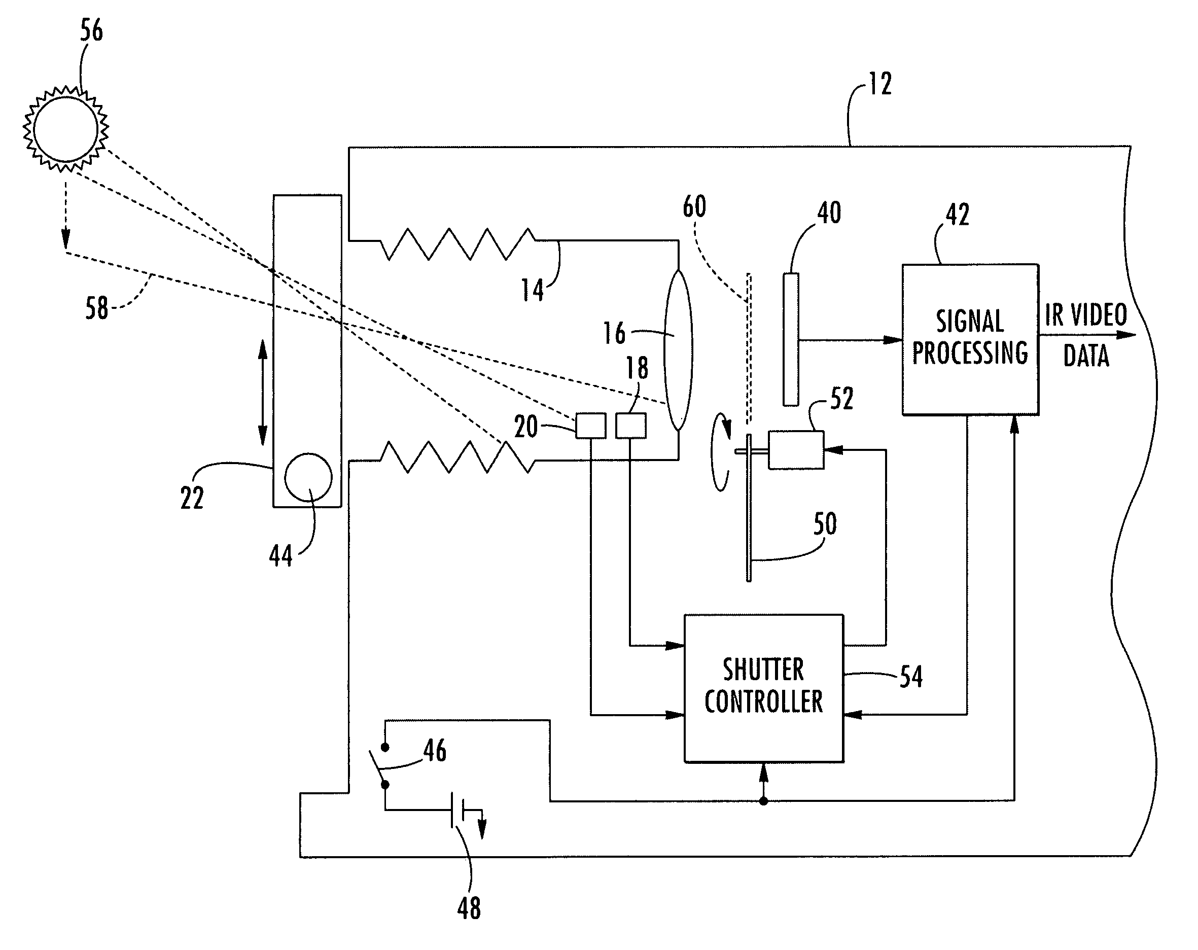
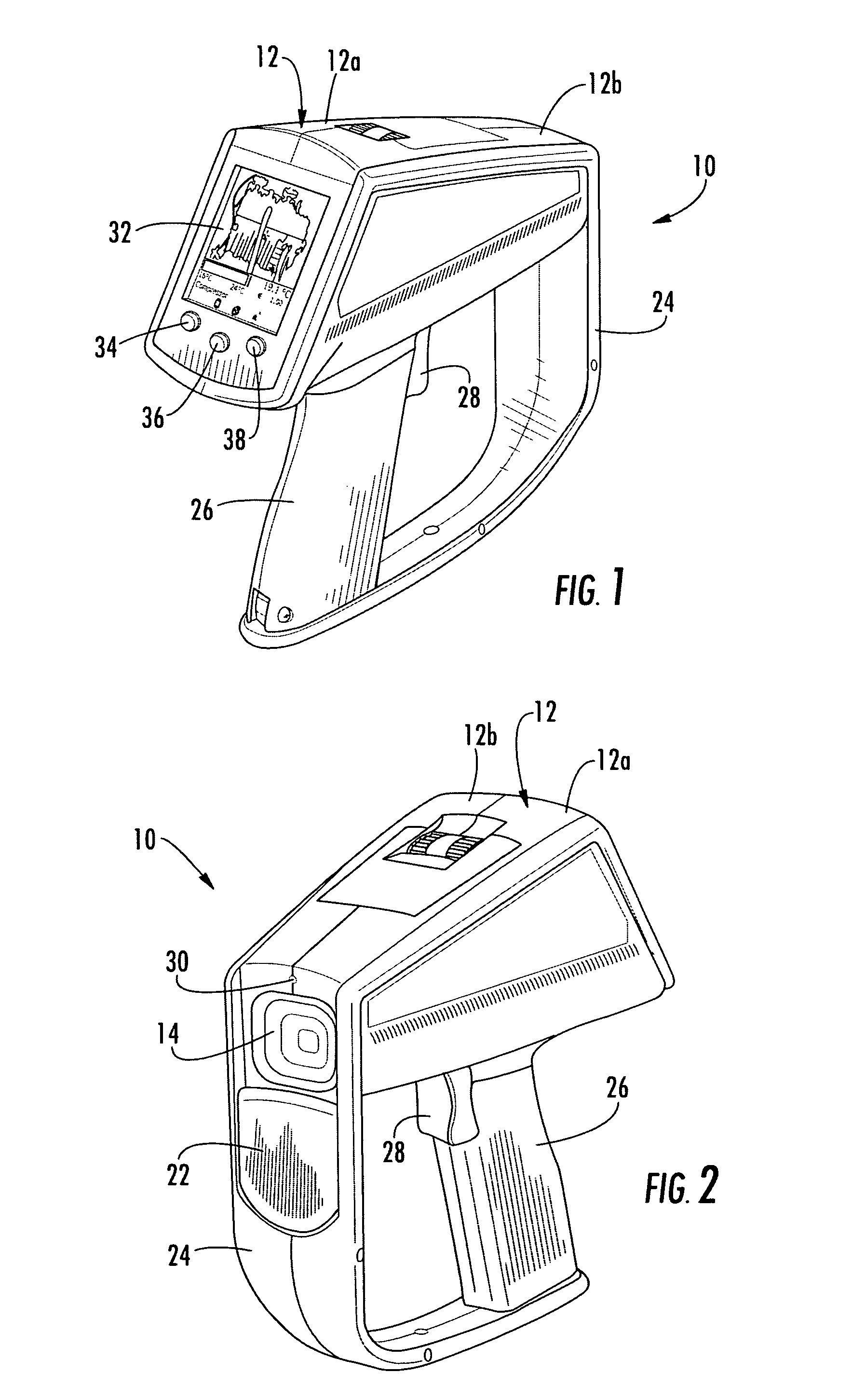
[0019]FIGS. 1 and 2 illustrate a thermal imager 10 constructed in accordance with the present invention. Imager 10 includes a housing 12 in which the components of a thermal image camera are located. Preferably, housing 12 is formed by complementary left and right housing portions 12a and 12b which are joined together during assembly. While any suitable material can be utilized, housing portions 12a and 12b are preferably formed of a rigid high impact plastic material. Selected regions of housing 12 may be desirably overmolded with a softer polymeric material.

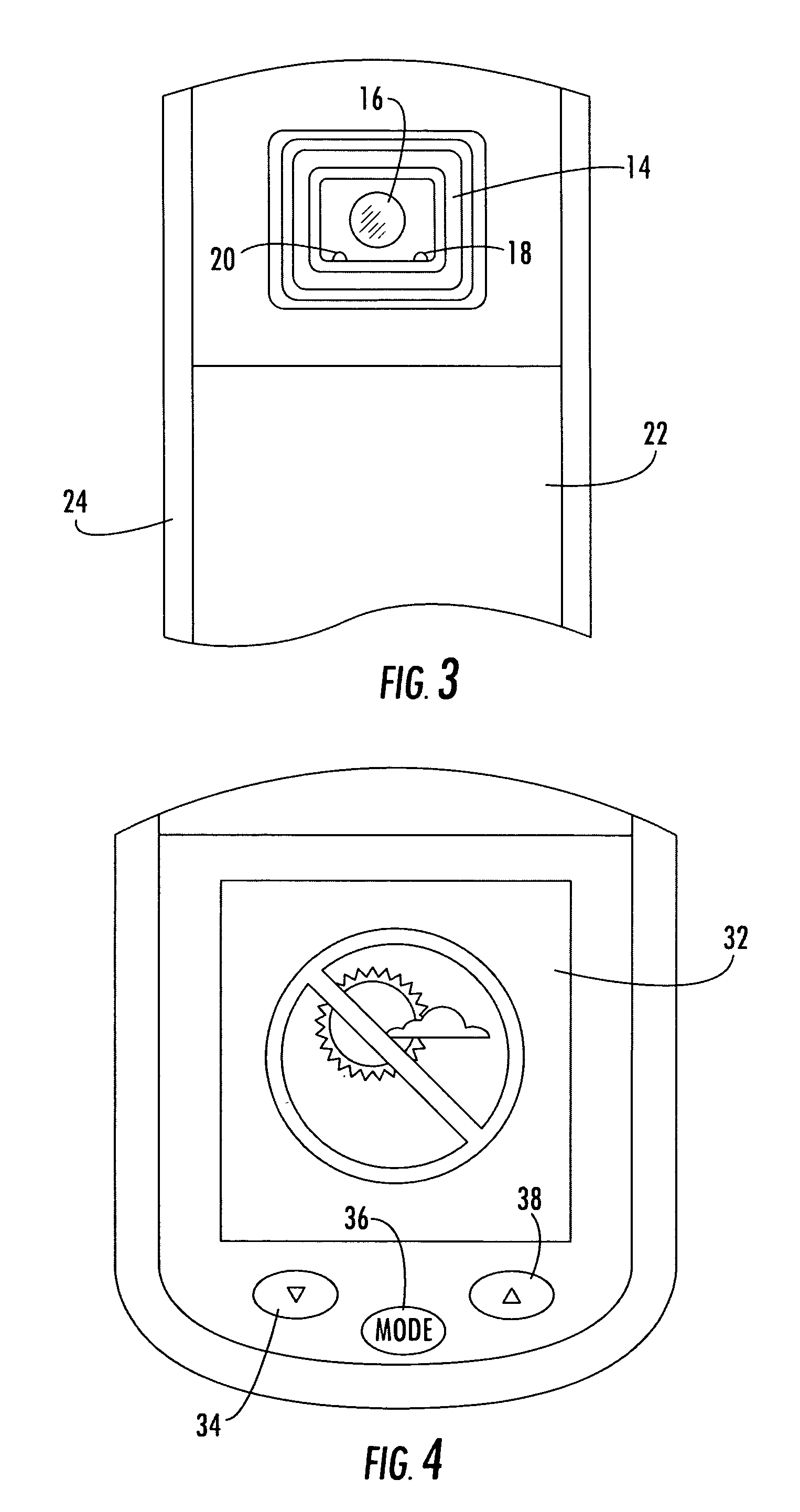
[0020]Referring now also to FIG. 3, housing 12 includes a front portion defining a hood 14 where the device's lens 16 is located. One skilled in t...


PUM


Abstract

A thermal imaging apparatus comprises a housing defining an entrance pupil for ingress of imaging radiation. At least one light sensor is positioned forward of the entrance pupil. An electronic imaging device such as a focal plane array is located in the housing rearward of the entrance pupil for converting imaging radiation to electrical signals for further processing. The apparatus further includes a shutter having an open position and a closed position. In the closed position, the shutter is located between the entrance pupil and the electronic imaging device so as to inhibit exposure of the electronic imaging device to incident radiation. Circuitry is provided for selectively operating the shutter to be in the closed position based on signals produced at the light sensor.

Description

BACKGROUND OF THE INVENTION[0001]The present invention relates generally to thermal imagers. More particularly, the invention relates to a thermal imager having a mechanism for protecting internal components from damage due to sunlight and other high energy radiation sources.[0002]Thermal imaging cameras are widely used in a variety of applications, such as predictive maintenance in industrial facilities. While past imagers often utilized a scanning technique, modern imagers generally incorporate an infrared (IR) focal plane array (FPA) for producing the thermal image. Focal plane arrays have many advantages, such as the speed at which successive images can be produced for display.[0003]One drawback of current focal plane arrays is their susceptibility to damage when exposed to high radiation sources such as sunlight. For example, a user may inadvertently damage the focal plane array (and thus the overall imager) by waving the imager's lens in a direction toward the sun. Thus, a nee...

Claims


Application Information

Patent Timeline
03 Feb 2009
Publication
US7484885B1
IPC
G01J5/06
CPC
G01J5/02; G01J5/025; G01J5/026; G01J5/0265; G01J5/08; G01J5/0834; G01J5/089; G01J5/10
Inventors
CARLSON, PAUL S.; HEINKE, THOMAS