System and method for controlling pressure in a surgical tourniquet

a technology of tourniquet and pressure control, which is applied in the field of surgical tourniquets, can solve the problems of nerve and vascular injuries, inability to control the pressure of the surgical tourniquet, and the flow of the anesthesia past the barrier and into the patient's body,

Inactive Publication Date: 2009-02-03
STRYKER CORP
View PDF28 Cites 22 Cited by
  • Summary
  • Abstract
  • Description
  • Claims
  • Application Information

AI Technical Summary

Benefits of technology

[0012]The flow of blood past a tourniquet may create an indication which may be detected and transmitted to a tourniquet controller. The indication may be pressure variations in the veins and arteries of an extremity to which the surgical tourniquet is applied. These pressure variations may be a signal audible to a listener, or a variation of the cuff pressure caused by the pulsing associated with normal blood flow. These pressure variations may be transmitted from the surgical tourniquet to the controller via the fluid medium used to inflate the tourniquet. By incorporating a sensor to detect these signals, a feedback loop can be incorporated into the controller allowing the controller to detect blood flow past the tourniquet when the tourniquet is inflated. When blood flow past the pressure cuff of the surgical tourniquet is detected, the controller can increase pressure into the surgical tourniquet, thereby providing a means for ensuring that the flow of blood past the surgical tourniquet is occluded.

Problems solved by technology

Over-pressurization of a tourniquet can cause injury to a patient on whom the tourniquet is being used.
Neural and vascular injuries can occur due to the pressure in use causing physical trauma.
In addition to the constraints of simply using a surgical tourniquet to occlude blood flow, the use of the surgical tourniquet to provide a barrier to allow intravenous regional anesthesia (IVRA) raises additional concerns, particularly with the dangers associated with the flow of the anesthesia past the barrier and into the body of the patient.

Method used


Image

  • System and method for controlling pressure in a surgical tourniquet
  • System and method for controlling pressure in a surgical tourniquet
  • System and method for controlling pressure in a surgical tourniquet

Examples


Embodiment Construction

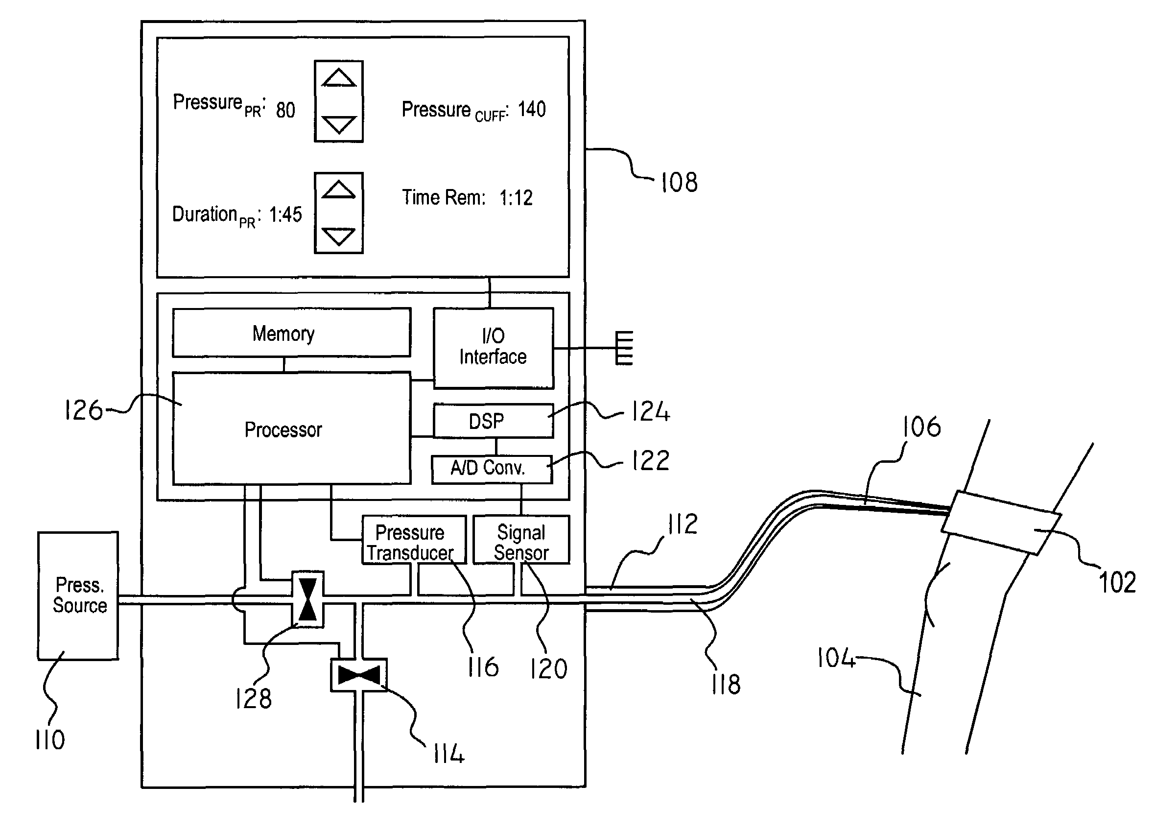
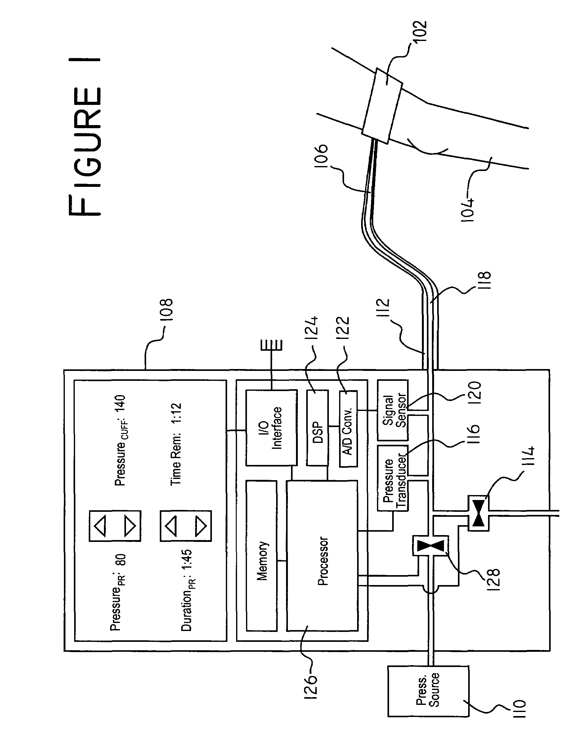
[0028]Referring now to FIG. 1, wherein like reference numerals indicate like elements, there is shown the components of an embodiment of the present invention. A surgical tourniquet is a pressure cuff 102 containing a pressure chamber (not shown) which extends around the circumference of an appendage 104 in which it is desired to occlude blood flow. By increasing the pressure in the pressure chamber, the pressure cuff 102 compresses the appendage 104 until the constriction pressure exceeds the blood pressure, at which point internal veins and arteries close due to the inability of the blood pressure to overcome the pressure applied by the pressure cuff 102.

[0029]The pressure in the pressure chamber is controlled by adding or releasing a pressure medium 106 to or from the pressure chamber. The pressure medium 106 is a fluid allowing flow from the controller 108 into the pressure chamber. Pressure changes made to the pressure medium 106 at a location remote from the pressure cuff 102 ...


PUM


Abstract

A system and method of controlling the pressure within a pressure cuff of a surgical tourniquet so as selectively to occlude blood flow within a portion of a limb of a patient, wherein a sensor determines when flow past the tourniquet is occurring so that corrective action may be taken, such as by increasing the pressure in the tourniquet or by notifying an operator of the flow past the tourniquet. The present invention may use an acoustic sensor to detect Korotkoff sounds indicating incipient blood flow past the tourniquet. When such signals are detected, the tourniquet controller may either incrementally increase the pressure in the tourniquet, or if a threshold would be exceeded by such an increase, signal an alarm indicative of the blood flow.

Description

[0001]The present application is a continuation in part of U.S. patent application Ser. No. 09 / 955,763, filed Sep. 19, 2001 issued as U.S. Pat. No. 6,605,103 on Aug. 12, 2003, which is a continuation in part of U.S. patent application Ser. No. 09 / 504,131, filed Feb. 15, 2000 now U.S. Pat. No. 6,475,228 which is a continuation of U.S. patent application Ser. No. 09 / 280,312. U.S. patent application Ser. No. 09 / 280,312 filed Mar. 29, 1999 issued as U.S. Pat. No. 6,051,016 on Apr. 18, 2000.FIELD OF THE INVENTION[0002]The present invention relates generally to surgical tourniquets. More particularly, the present invention relates to various aspects of a system and method for controlling pressure in a surgical tourniquet utilizing feedback from a flow detection sensor incorporated in the tourniquet control system.BACKGROUND[0003]Surgical tourniquets are widely used during surgical procedures to occlude the flow of blood in a portion of a limb during the procedure, particularly in connecti...

Claims


Application Information

Patent Timeline
Patent Type & Authority Patents(United States)
IPC IPC(8): A61B17/12A61BA61B5/0225A61B17/135
CPCA61B5/02208A61B5/0225A61B17/135A61B17/1355
Inventor HOVANES, MICHAEL E.SCHMITT, DON S.
Owner STRYKER CORP
Why Eureka
Try Eureka