Pneumatic spring vibration damper assembly unit

a technology of pneumatic springs and assembly units, which is applied in the direction of shock absorbers, mechanical equipment, transportation and packaging, etc., can solve the problems of premature impairment or failure of pneumatic spring vibration damper assembly units known from the state of the art, increase friction, and poor response characteristic of the vibration damper system, so as to improve the force transmission and the service life of such devices. the effect of significant prolonging

Inactive Publication Date: 2009-02-10
MENTOR GRAPHICS CORP +1
View PDF6 Cites 15 Cited by
  • Summary
  • Abstract
  • Description
  • Claims
  • Application Information

AI Technical Summary

Benefits of technology

[0006]Based on these drawbacks known from the state of the art, the object of the present invention is to improve a pneumatic spring vibration damper assembly unit of this type such that the service life of such devices can be significantly prolonged based on improved force transmission within the assembly unit.
[0008]The connection of the drag bearing arrangement and the connecting element present between the piston rod and the piston makes it possible for the piston rod, as a consequence of displacements of the chassis-side assembly units, to which the piston rod is fixed, to be able to follow these displacements, without being subject to bending. The displacement of the chassis-side assembly unit rather leads to an angular deflection of the longitudinal axis of the piston rod in relation to the central longitudinal axis of the cylinder tube. However, the piston connected to the piston rod can continue to run easily within the cylinder tube due to the design according to the present invention, so that rapid response characteristic of the vibration damper system is guaranteed.
[0010]As a special embodiment variant of the drag bearing arrangement, it proved to be especially advantageous that this drag bearing arrangement has a bearing inner part, which is provided with a continuous recess adapted to the cross section of the piston rod, with a round outer contour of varying cross section in the form of a convex outer shape, which is surrounded by a bearing outer part with a corresponding concave inner recess adapted to the outer contour of the bearing inner part. This special drag bearing arrangement guarantees, similarly to a ball sleeve joint, easy pivoting of the piston rod out of the usual central longitudinal axis of the cylinder tube, and easy displaceability of the piston rod is also guaranteed at the same time. In addition, it may be advantageous to manufacture the bearing inner part of the drag bearing arrangement of a plastic in order to additionally reduce frictional losses.
[0014]Corresponding to another advantageous embodiment of the subject of the present invention, the piston rod may be accommodated at the second chassis-side assembly unit in another drag bearing arrangement, which makes possible small angular deviations of the central axis of the piston rod at right angles to the plane of fastening of the chassis-side assembly unit.

Problems solved by technology

It proved to be disadvantageous in the existing constructions that due to possibly occurring displacements between the assembly units mentioned, the piston rod connecting the body-side assembly unit to the chassis-side assembly unit is frequently subject under normal operating conditions to bending loads, which lead, due to the piston being connected to the piston rod, to increased friction in the cylinder tube of the vibration damper system, and, as a result hereof, to a poorer response characteristic of the vibration damper system.
In connection with the usual situations occurring during operation, this leads, as a rule, prematurely to impairment or failure of the pneumatic spring vibration damper assembly units known from the state of the art.

Method used


Image

  • Pneumatic spring vibration damper assembly unit
  • Pneumatic spring vibration damper assembly unit
  • Pneumatic spring vibration damper assembly unit

Examples


Embodiment Construction

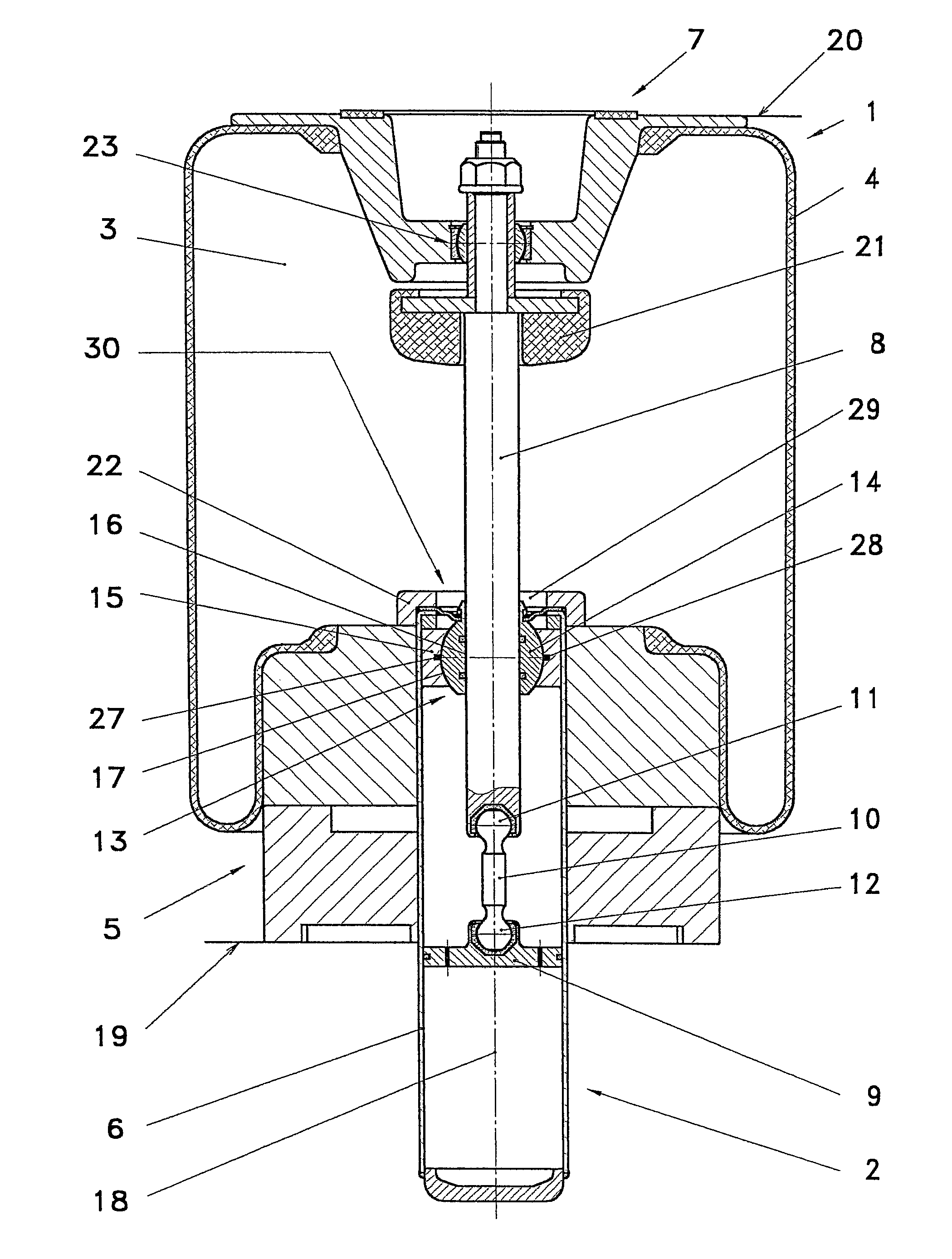
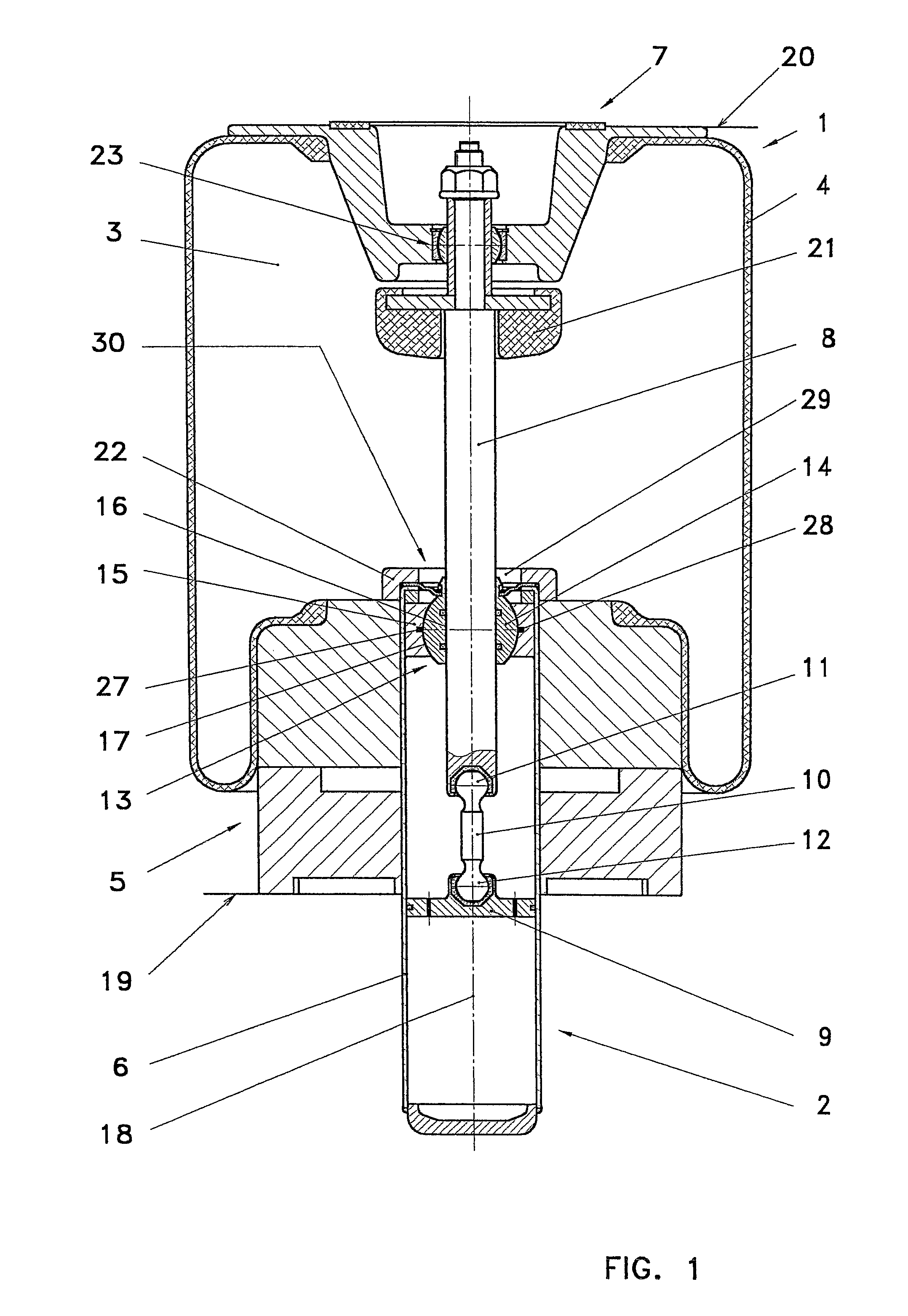
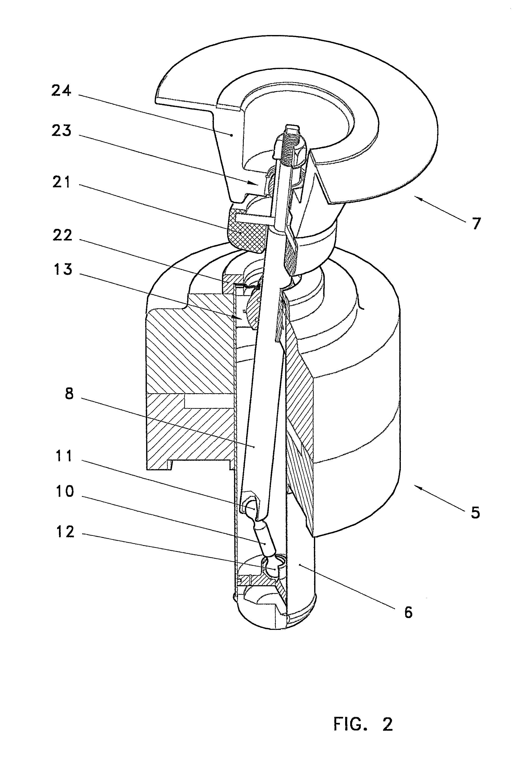
[0023]Referring to the drawings in particular, FIG. 1 shows a pneumatic spring 1 as an assembly unit together with a vibration damper system 2. The pneumatic spring 1 comprises essentially two assembly units, which are movable in relation to one another, the first assembly unit 5 being fixed to the motor vehicle on the body side and accommodating a cylinder tube 6 of the vibration damper system 2, and a chassis-side assembly unit 7, which is fixed, for example, to a wheel suspension of a motor vehicle. The roll bellows 4 that sealingly connects the aforementioned two assembly units 5 and 7 to one another leads to the formation of an air chamber 3 with variable volume between the components. This air chamber is filled with compressed air, which forms the suspension medium of the pneumatic spring. The body-side assembly unit 5 and the chassis-side assembly unit 7 are connected, corresponding to FIG. 1, by a piston rod 8, which is provided at its lower, body-side end with a piston 9, w...


PUM


Abstract

A pneumatic spring-vibration damper unit is provided for absorbing shocks on wheels and chassis parts of motor vehicles. A variable air chamber is delimited by a rolling bellows which is disposed between a first subassembly that is fixed to the vehicle body and is provided with a vibration damper system and a second subassembly that is fixed to the vehicle chassis and is movable therewith. A piston rod connects the first subassembly located at the vehicle body end and the second subassembly located at the chassis end and whose free end located at the vehicle body end is accommodated inside a cylinder tube of the vibration damper system so as to be longitudinally movable by means of a piston. The piston rod (8) is guided within the cylinder tube (6) of the vibration damper system (2) so as to be longitudinally movable with the aid of a drag bearing arrangement (13). This allows the longitudinal axis of the piston rod to be angularly deflected relative to the central longitudinal axis (18) of the cylinder tube (6) while a joining element (10) which is fastened to the piston rod (8) and the piston (9) by a respective ball-and-socket joint unit (11, 12) is positioned between the piston rod (8) and the piston (9).

Description

CROSS REFERENCE TO RELATED APPLICATIONS[0001]This application is a United States National Phase application of International Application PCT / DE2005 / 001159 and claims the benefit of priority under 35 U.S.C. § 119 of German Patent Application DE 10 2004 032 411.5 filed Jul. 2, 2004, the entire contents of which are incorporated herein by reference.FIELD OF THE INVENTION[0002]The present invention pertains to a pneumatic spring vibration damper assembly unit for the suspension of wheels and chassis components of motor vehicles, with a variable air chamber limited by a roll bellows, in which the roll bellows is arranged between a first assembly unit, which is fixed on the body side and is provided with a vibration damper system, and a second assembly unit, which is fixed to the chassis of the motor vehicle and is able to move together with same.BACKGROUND OF THE INVENTION[0003]Such an assembly unit is known, for example, from DE 199 59 839 A1. A pneumatic spring combined with a vibratio...

Claims


Application Information

Patent Timeline
Patent Type & Authority Patents(United States)
IPC IPC(8): F16F9/04
CPCB60G15/14F16F9/05F16F9/3228F16F9/367F16F9/54B60G2202/152B60G2202/314B60G2204/126B60G2204/1262B60G2204/4402B60G2204/45B60G2206/911F16F9/084
Inventor BRUNNEKE, HANS-GERDLOESCHE, CHRISTIAN
Owner MENTOR GRAPHICS CORP
Why Eureka
Try Eureka