Antiskid control unit and data collection system for vehicle braking system

a technology of anti-skid control and data collection system, which is applied in the field of vehicle braking system, can solve the problems of increasing the cost and weight of aircraft, inconvenient maintenance crew of landing gear, and large length of wires from sensors to both the anti-skid control unit and the data concentrator, so as to reduce the cost and weight of the anti-skid control system, reduce the cost and weight of the system, and improve the effect of data collection efficiency and convenien

Active Publication Date: 2009-02-10
HYDRO AIRE AEROSPACE CORP
View PDF26 Cites 50 Cited by
  • Summary
  • Abstract
  • Description
  • Claims
  • Application Information

AI Technical Summary

Benefits of technology

[0010]In a detailed facet of the system, the wheel speed transducer includes a magnetic device associated with the wheel and a sensor device associated with the axle. The sensor device is adapted to sense the magnetic field produced by rotation of the magnetic device and output signals to the processor. As such, the system detects wheel speed without direct contact between rotating and stationary parts. The output signals from the magnetic sensor are wheel speed data signals. These signals are used by the processor to perform antiskid control functions. By positioning the antiskid processor at the axle, as opposed to the electronic equipment bay, and near the wheel speed transducer, the invention substantially reduces antiskid control system cost and weight by eliminating the need for large amounts of aircraft wiring between the transducer and the processor.
[0011]In other detailed aspects of the invention, the system includes one or more additional sensors for providing additional operation information data to the processor for storage in the data concentrator. For example, a tire pressure sensor may be included to provide tire pressure data. Such a tire pressure sensor may include a transmitting device with a pressure sensor at one end in communication with the tire interior and a transmitting antenna at the other end for transmitting pressure sensor signals. The sensor may further include a receiving device in communication with the processor that is adapted to receive signals from the transmitting antenna. In a more detailed aspect, the transmitting device is associated with the axle while the receiving device is associated with the wheel. Using a transmitter and receiver pair as such allows for the passing of data from within the rotating wheel to the processor within the stationary axle. Other possible sensors for use with the system include brake temperature sensors and brake torque sensors. Once again, by positioning the processor at the axle and near the pressure, temperature and torque sensors, the invention substantially reduces system cost and weight by eliminating the need for large amounts of aircraft wiring that typically run between the sensors and the processor.
[0012]In another aspect, the means for downloading the operation information from the data concentrator includes a receiving antenna at the wheel and a transmitting antenna at the axle. The transmitting antenna is in communication with the data concentrator and transmits the operation information data to the receiving antenna which is in communication with a data port. An external device may be connected to the data port in order to download the data from the data concentrator. Access to the operation information data directly at the wheel, provides for more efficient and convenient data collection.

Problems solved by technology

The need for great lengths of wire from the sensors to both the antiskid control unit and the data concentrator tends to increase the cost and weight of the aircraft.
This is often inconvenient for the landing gear maintenance crew, in that the data concentrator is located a distance from the landing gear itself.

Method used


Image

  • Antiskid control unit and data collection system for vehicle braking system
  • Antiskid control unit and data collection system for vehicle braking system
  • Antiskid control unit and data collection system for vehicle braking system

Examples


Embodiment Construction

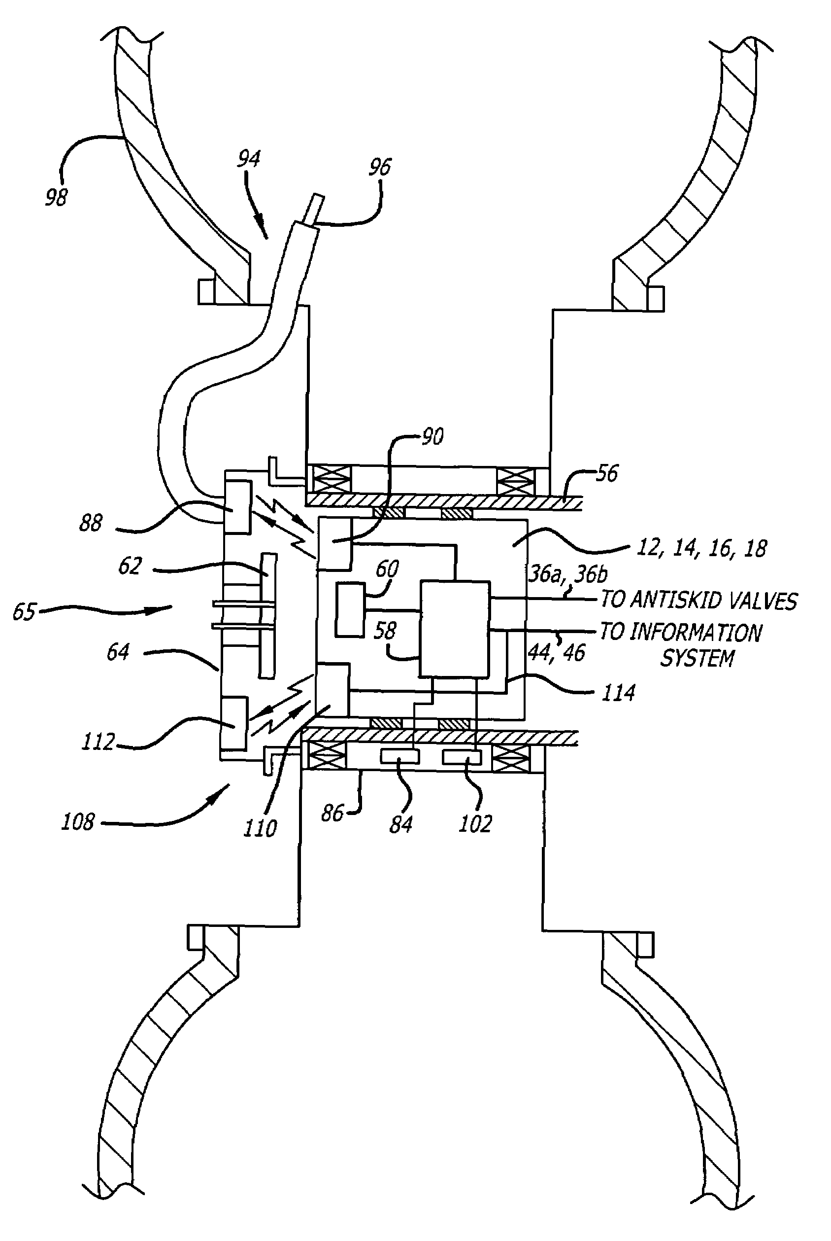
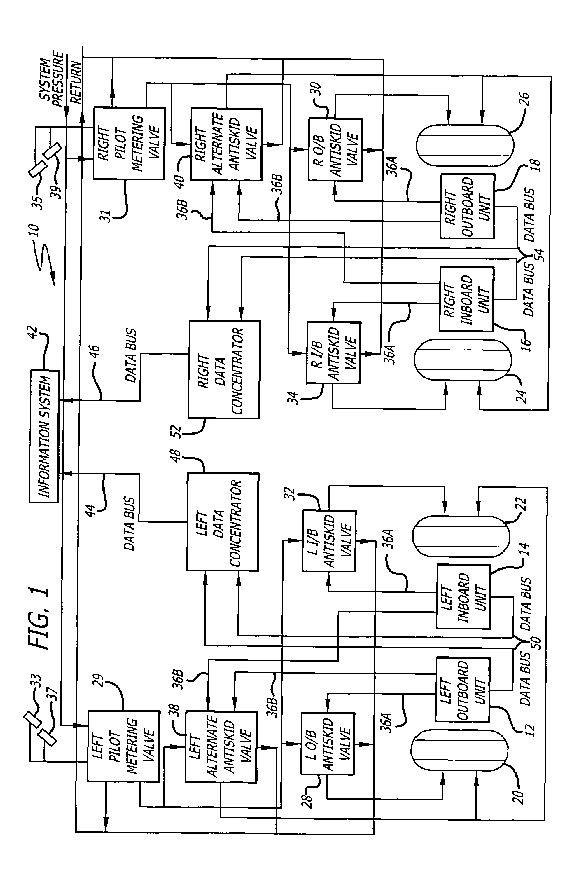
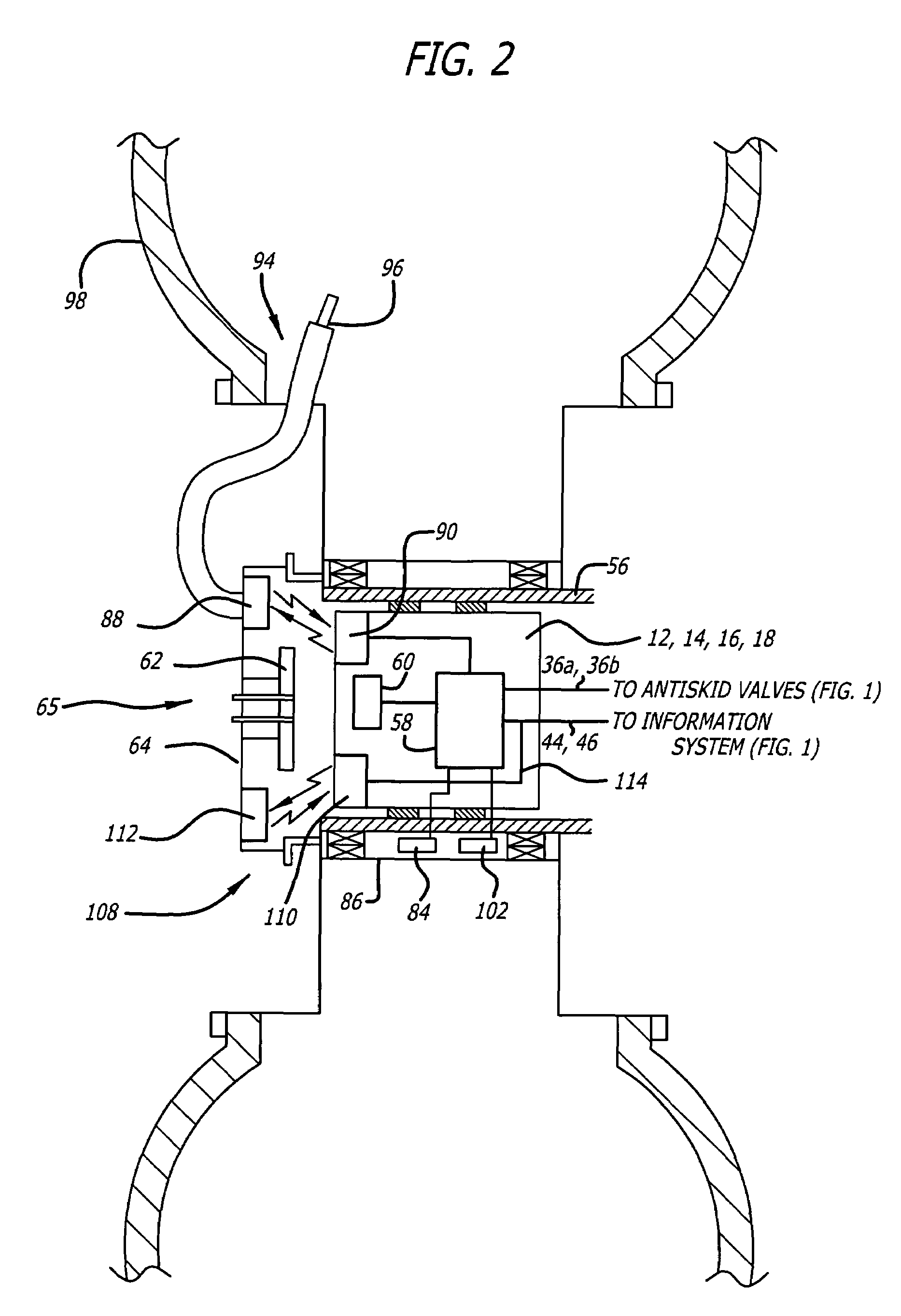
[0017]Referring now to the drawings, wherein the reference numerals denote like or corresponding parts throughout the figures, and particularly to FIG. 1, there is shown a schematic block diagram of an antiskid system 10 configured in accordance with the present invention. Although shown within the context of an aircraft landing gear, use of the system 10 is not limited to aircraft and may be used in other non-aircraft vehicles such as trains, trucks and automobiles.

[0018]As shown in FIG. 1, the antiskid system 10 includes a left outboard antiskid unit 12, a left inboard antiskid unit 14, a right inboard antiskid unit 16 and a right outboard antiskid unit 18. Each antiskid unit 12, 14, 16, 18 is associated with one of the four wheels 20, 22, 24, 26 of the aircraft landing gear. Details of the antiskid units 12, 14, 16, 18 are provided below. The antiskid system 10 also includes left and right outboard antiskid valves 28, 30 and left and right inboard antiskid valves 32, 34. The anti...


PUM


Abstract

A wheel speed transducer including a magnetic device associated with a wheel and a sensor device associated with the axle of the wheel provides data indicative of the velocity of the wheel. A processor located at the axle receives the wheel speed data and processes it to perform antiskid control functions. The velocity data is stored in a data concentrator also associated with the axle. A tire pressure sensor, a brake temperature sensor and a brake torque sensor, each associated with the wheel, send data to the processor at the axle, for storage in the data concentrator. A transmitting antenna associated with the axle and in communication with the data concentrator transmits stored data to a receiving antenna associated with the wheel. A data port at the wheel and in communication with the receiving antenna provides an interface to an external device for receiving the data.

Description

BACKGROUND OF THE INVENTION[0001]1. Field of the Invention[0002]The invention relates generally to vehicle braking systems, and more particularly, to an antiskid system that controls the deceleration of the vehicle wheels and collects information related to the operation of the vehicle braking system.[0003]2. Description of Related Art[0004]Antiskid braking systems have been provided on commercial and large turbine aircraft to aid in the deceleration of aircraft upon landing. Modern antiskid systems typically optimize braking efficiency by adapting to runway conditions and other factors affecting braking to maximize deceleration, corresponding to the level of brake pressure selected by the pilot. In conventional antiskid braking systems, brakes are typically applied mechanically through a metering valve by the pilot. As soon as the wheel brake pressure approaches the skid level, such as when an initial skid is detected, the antiskid control system is initialized.[0005]The electronic...

Claims


Application Information

Patent Timeline
Patent Type & Authority Patents(United States)
IPC IPC(8): B60T8/68B64C27/22B60T8/17B60T8/171G01P1/12G01P1/16G01P3/44G06F17/00G07C5/08
CPCB60T8/1703B60T8/171G01P1/122G01P1/16G01P3/443G07C5/085G01L5/28
Inventor GOWAN, JOHNDEVLIEG, GARY
Owner HYDRO AIRE AEROSPACE CORP
Why Eureka
Try Eureka