
Magnetostrictive multilayer sensor and method for producing a sensor

a multi-layer sensor and magnetic field technology, applied in the direction of fluid pressure measurement, fluid pressure measurement by electric/magnetic elements, instruments, etc., can solve the problems of increased chip area, increased production cost, and additional effort, etc., to achieve the effect of increasing the production cost of the sensor

Inactive Publication Date: 2009-02-17
INFINEON TECH AG
View PDF34 Cites 44 Cited by
  • Summary
  • Abstract
  • Description
  • Claims
  • Application Information

AI Technical Summary

Benefits of technology

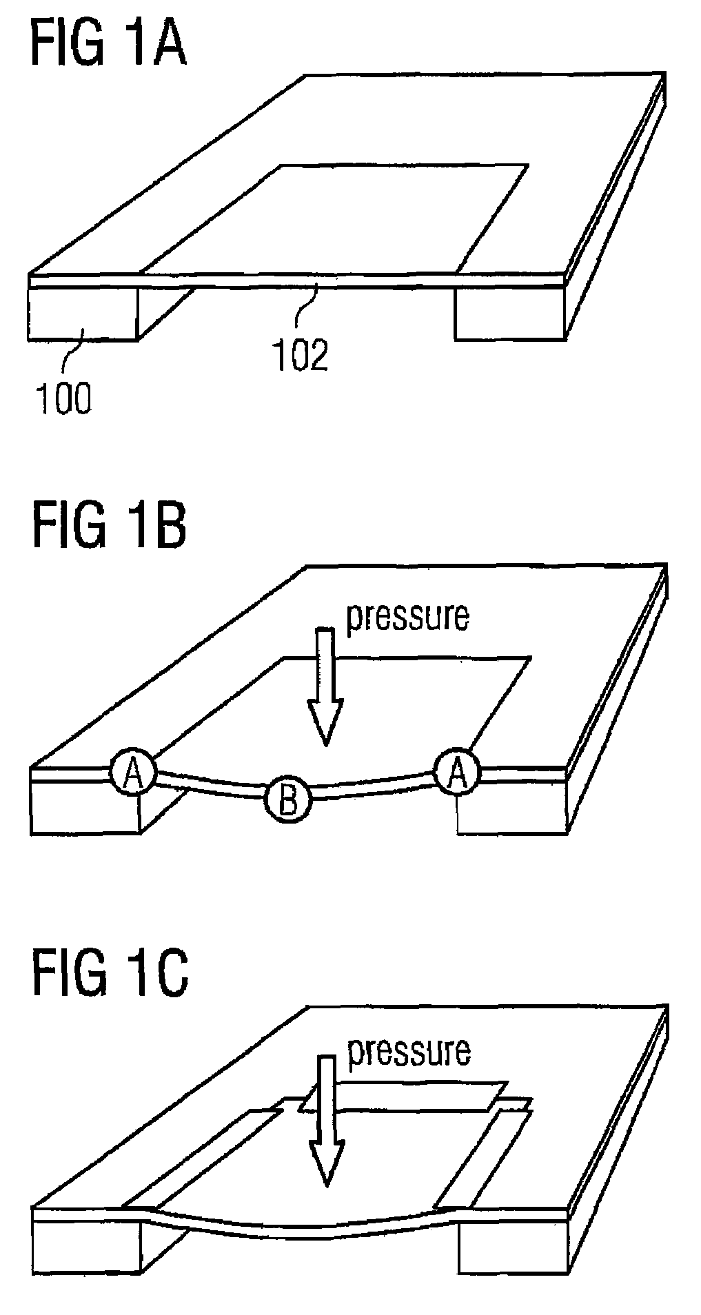
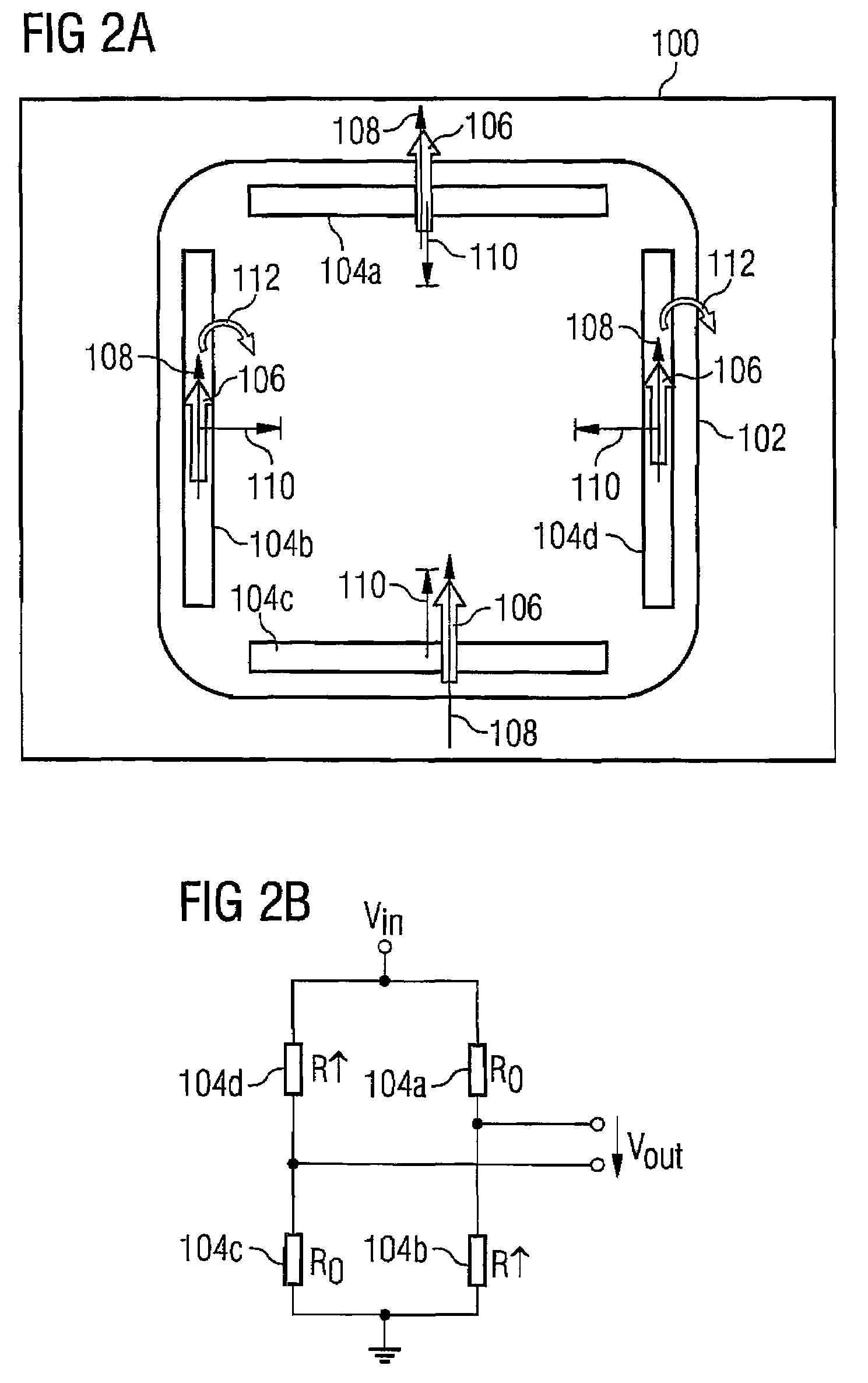
The patent describes a sensor that can detect changes in its mechanical deformation. It consists of two layers of magnetostrictive material that are connected to each other. When the sensor is mechanically deformed, the electric resistance of one of the layers changes in response to the deformation, while the other layer remains unaffected. This change in resistance can be measured to determine the amount of deformation. The sensor is made using a spin-valve sensor design, which allows for the detection of changes in magnetic hard layer magnetization. The technical effect of this invention is the ability to accurately measure mechanical deformation through the use of a magnetostrictive sensor design.

Problems solved by technology

Thereby, the capacitance swings are so small, that significant effort has to be made in signal processing, which results in an increased chip area.
Further, the increased signal processing effort leads to additional cost increase of production, since additional effort is required for realizing the corresponding circuits.
The additional effort also increases the production cost of the sensors, where it would be desirable to provide a sensor with lower production cost, due to the numerous applications for which pressure sensors are suitable, and due to the fierce competition.

Method used


Image

  • Magnetostrictive multilayer sensor and method for producing a sensor
  • Magnetostrictive multilayer sensor and method for producing a sensor
  • Magnetostrictive multilayer sensor and method for producing a sensor

Examples


Embodiment Construction

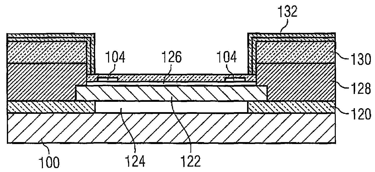
[0022]According to another embodiment, a method for producing a sensor may have the steps of: generating a mechanically deformable area in a substrate; generating a first magnetostrictive multilayer sensor element and a second magnetostrictive multilayer sensor element, each at least partly in the mechanically deformable area, wherein the same are implemented such that when generating a mechanical deformation of the of the mechanically deformable area, the electric resistance of the first magnetostrictive multilayer sensor element changes in opposition to the electric resistance of the second magnetostrictive multilayer sensor element, or the electric resistance of the first magnetostrictive multilayer sensor element remains unchanged, wherein the first and second magnetostrictive multilayer sensor elements are spin-valve sensor elements and a magnetization of the magnetically hard layer of the first sensor element and the second sensor element have the same direction; and connectin...


PUM

PropertyMeasurementUnit
thicknessaaaaaaaaaa
thicknessaaaaaaaaaa
anglesaaaaaaaaaa

Abstract

A sensor has a substrate in which a mechanically deformable area is formed. A first magnetostrictive multilayer sensor element and a second magnetostrictive multilayer sensor element are formed in the mechanically deformable area, wherein the first magnetostrictive multilayer sensor element and the second magnetostrictive multilayer sensor element are connected to each other and implemented such that when generating a mechanical deformation of the mechanically deformable area, the electric resistance of the first magnetostrictive multilayer sensor element changes in an opposite way to the electric resistance of the second magnetostrictive multilayer sensor element, or the electric resistance of the first magnetostrictive multilayer sensor element remains unchanged.

Description

RELATED APPLICATION[0001]This application is a continuation of International Application No. PCT / EP2005 / 007262 filed Jul. 5, 2005, which designates the United States, and claims priority to German application number DE 10 2004 032 484.0 filed Jul. 5, 2004.TECHNICAL FIELD[0002]The present invention relates to magnetostrictive multilayer sensors for detecting mechanical deformation.BACKGROUND[0003]Nowadays, magnetostrictive multilayer systems, such as spin-valve systems, are used in a plurality of applications. One field of application that has increased in importance recently comprises the usage of magnetostrictive GMR / TMR resistor structures as pressure sensors.[0004]Pressure sensors operate generally according to the principle of deflection of moveable membranes or other moveable elements, by pressure impact, wherein the membrane deflection represents a measure for the applied pressure. Thereby, the membranes of the pressure sensors can be realized in silicon technology via bulk mi...

Claims


Application Information

Patent Timeline
Patent Type & Authority Patents(United States)
IPC IPC(8): G01L3/02G01B7/16G01B7/24G01L1/12G01L9/16
CPCG01L1/12G01L9/16
Inventor RUEHRIG, MANFREDSCHMITT, STEPHANZIMMER, JUERGEN
Owner INFINEON TECH AG
Learn More