Disc brake actuating apparatus with parking-brake operating mechanism

a technology of operating mechanism and disc brake, which is applied in the direction of mechanically actuated brakes, actuators, braking elements, etc., can solve the problems of difficult to obtain machining technique, and difficult to achieve a high boost ratio within the range of an allowable lever stroke, etc., to suppress a power transmission loss, reduce the rotational frictional resistance of the cam shaft, and impart the effect of braking for

Inactive Publication Date: 2009-02-17
AKEBONO BRAKE IND CO LTD
View PDF9 Cites 14 Cited by
  • Summary
  • Abstract
  • Description
  • Claims
  • Application Information

AI Technical Summary

Benefits of technology

[0008]One or more embodiments of the present invention provide a disc brake actuating apparatus provided with a parking-brake operating mechanism which can reduce a rotational frictional resistance of a cam shaft, and can suppress a power transmission loss even when an axial thrust increases, and can impart a braking force of a high boost ratio.

Problems solved by technology

In any of these types, however, it is difficult to obtain a high boost ratio within the range of an allowable brake lever stroke.
The formation of the sliding holes 6a (having the width across flats for the cam shaft 2) by grinding from the outside of the caliper 6 (This process is separate from a process of forming the sliding holes 6b) has been relatively difficult from the viewpoint of a machining technique, and has required much time.
And besides, although the toggle link 3 is slidably supported between the cam shaft 2 and the adjusting spindle 4 while the toggle link 5 is slidably supported between the cam shaft 2 and the caliper 6, a frictional resistance of a contact portion of each toggle link increases when an axial thrust increases, and this has led to a power transmission loss.

Method used


Image

  • Disc brake actuating apparatus with parking-brake operating mechanism
  • Disc brake actuating apparatus with parking-brake operating mechanism
  • Disc brake actuating apparatus with parking-brake operating mechanism

Examples


Embodiment Construction

[0048]Embodiments of the invention will be described with reference to the accompanying drawings.

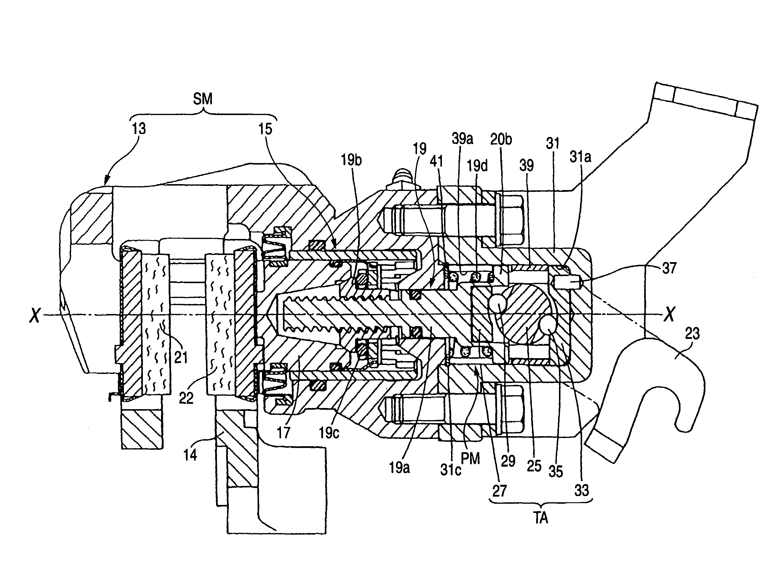
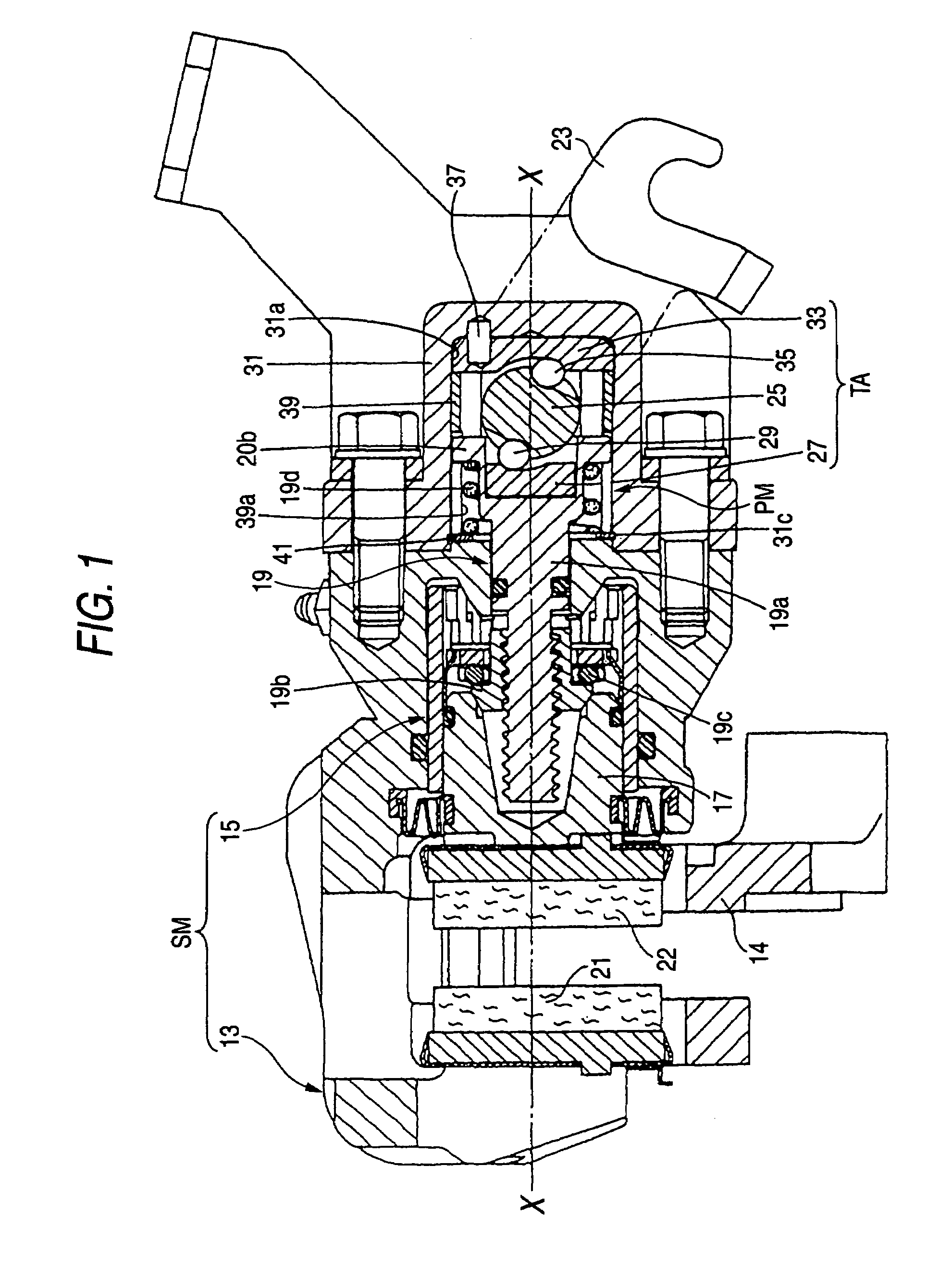
[0049]As shown in FIG. 1, a disc brake actuating apparatus of the invention provided with a fluid-operated service brake mechanism (SM) including a caliper 13 and a piston assembly 15, and the parking-brake operating mechanism (PM). The piston assembly 15 comprises a piston 17 which receives a fluid pressure to slide within the caliper 13 upon application of service braking, and an adjuster assembly 19 for compensating for wear of brake pads and also for preventing excessive adjustment. The caliper 13 is slidably supported on a fixed support member 14.

[0050]The adjuster assembly 19, used here, is of the known reversible screw type. This reversible screw-type adjuster includes the adjusting spindle 19a having a reversible screw, an adjusting sleeve 19b threaded on the spindle 19a, a bearing 19c for supporting the angular movement of the adjusting sleeve 19b, and a spring 19d . When wear o...


PUM


Abstract

A parking-brake operating mechanism is provided with an adjusting spindle, a cam shaft to which a parking lever is connected, and a thrust transmitting assembly disposed between the cam shaft and the adjusting spindle. The thrust transmitting assembly includes a rolling roller which can roll between the cam shaft and the adjusting spindle. Rolling curved surfaces are provided respectively at the cam shaft and the adjusting spindle. The rolling roller is disposed in contact with the rolling curved surfaces.

Description

[0001]The present application claims foreign priority based on Japanese Patent Application No. P.2004-357237, filed on Dec. 9, 2004, the contents of which are incorporated herein by reference.BACKGROUND OF THE INVENTION[0002]1. Field of the Invention[0003]The present invention relates to a disc brake actuating apparatus having a parking-brake operating mechanism provided at one end portion of a caliper slidably supporting a piston containing an adjuster mechanism.[0004]2. Related Art[0005]As conventional parking-brake operating mechanisms of a disc brake actuating apparatus, there are known the type employing toggle links, the type employing a ball ramp and the type employing a cam. In any of these types, however, it is difficult to obtain a high boost ratio within the range of an allowable brake lever stroke. In order to obtain high boost ratio with a limited brake lever stroke, JP-A-60-065920 discloses a parking-brake operating mechanism in which toggle links are arranged symmetri...

Claims


Application Information

Patent Timeline
Patent Type & Authority Patents(United States)
IPC IPC(8): F16D55/26F16D65/14
CPCF16D65/18F16D65/567F16D2121/02F16D2121/14F16D2123/00F16D2125/28F16D2125/30F16D2127/007
Inventor MAEHARA, TOSHIFUMI
Owner AKEBONO BRAKE IND CO LTD
Why Eureka
Try Eureka