Optical displacement sensor

a technology of optical displacement sensor and optical fiber, which is applied in the direction of optical radiation measurement, force/torque/work measurement apparatus, instruments, etc., can solve the problems of light loss and increase power consumption, and achieve the effects of enhancing accuracy, further and efficient introduction of optical fiber

Inactive Publication Date: 2009-02-17
MINEBEA CO LTD
View PDF4 Cites 33 Cited by
  • Summary
  • Abstract
  • Description
  • Claims
  • Application Information

AI Technical Summary

Benefits of technology

[0010]The present invention has been made in light of the above circumstances, and it is an object of the present invention to provide an optical displacement sensor structure which uses one light source, especially, for a plurality of light receiving elements, and which overcomes the problem of light loss while successfully enabling downsizing, and also to provide an external force detecting device incorporating such an optical displacement sensor structure.
[0011]In order to achieve the object, according to a first aspect of the present invention, there is provided an optical displacement sensor structure including: a reference segment and a measurement segment; one light source disposed at the reference segment (or the measurement segment); at least one light receiving element disposed at the measurement segment (or the reference segment) that does not have the one light source disposed thereat; and at least one optical fiber, wherein light emitted from the light source is introduced into the optical fiber from the circumferential surface of the optical fiber and exits out from the end face of one end portion of the optical fiber so as to proceed toward the light receiving element, whereby the light emitted from the light source is received by the light receiving element, and displacement of the measurement segment relative to the reference segment with regard to two axis directions in a plane perpendicular to the optical axis of the light emitted from the light source can be measured according to light receiving conditions. In the structure described above, the light emitted from the light source can be introduced efficiently into the optical fiber without suffering light loss.
[0012]In the first aspect of the present invention, the optical fiber may be wound to form a coil, the light source may be disposed to the central axis of the coil so that the light from the light source is introduced into the optical fiber from the inner circumference of the coil, and the end face of the one end portion of the optical fiber may be disposed so as to oppose the light receiving element. Since the inner circumference of the coil as a light entrance surface constitutes a large area, the light emitted from the light source can be introduced efficiently into the optical fiber. And, the structure described above enables downsizing.

Problems solved by technology

Conventionally, in a six-axis force sensor using three optical displacement sensors, a light source and a light receiving element must be provided at each optical displacement sensor thus requiring a plurality (three) of light sources, which results in increased power consumption.
With this structure, there is a lot of light leaking at the bent / curved portion causing a problem of light loss.

Method used


Image

  • Optical displacement sensor
  • Optical displacement sensor
  • Optical displacement sensor

Examples


Embodiment Construction

[0033]Exemplary embodiments of the present invention will hereinafter be described with reference to the accompanying drawings. The embodiments described below each refer to an optical displacement sensor applicable to an optical six-axis force sensor, but the present invention is not limited to the application for use in an external force detecting device to detect six-axis force and has general applicability.

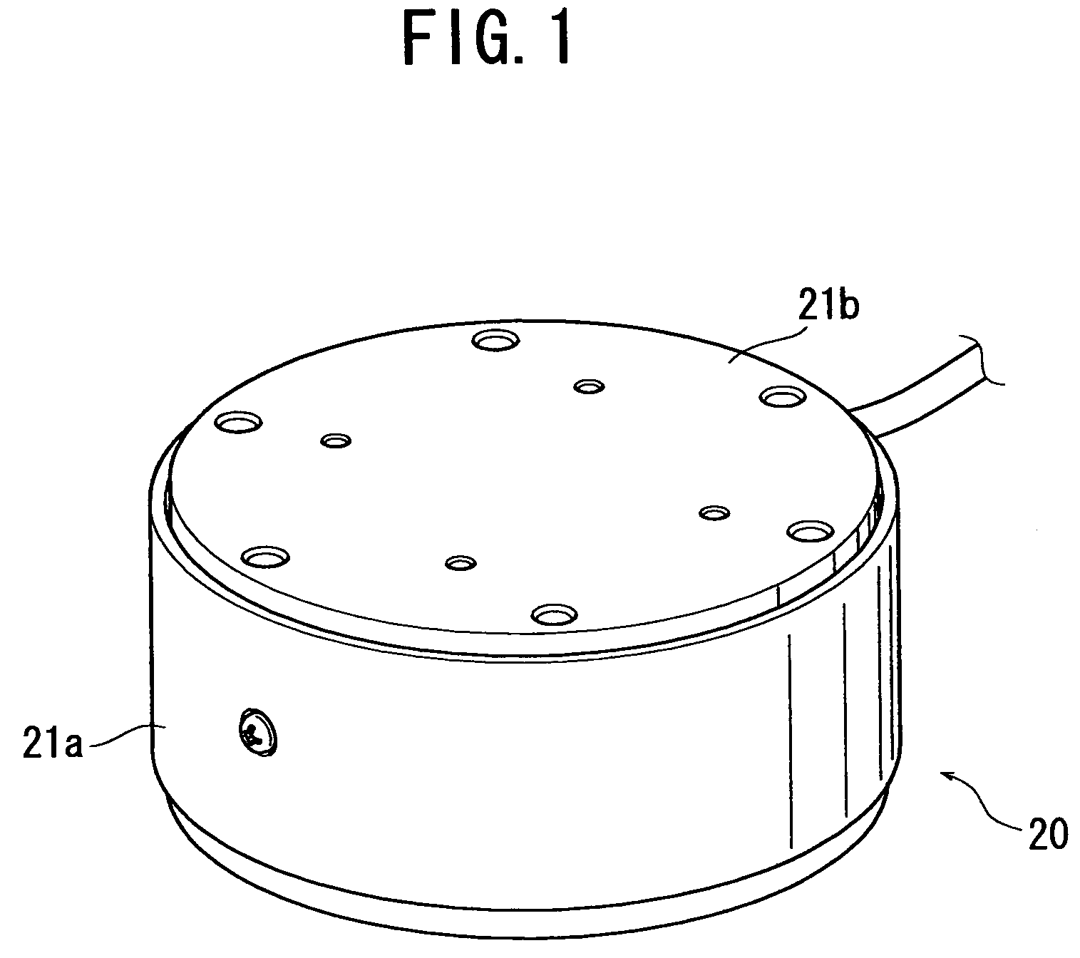
[0034]Referring to FIG. 1, a six-axis force sensor 20 according to a first embodiment of the present invention generally includes a main body 21a having a circular cylindrical configuration, a top lid 21b having a disk configuration, and a bottom lid (not shown).

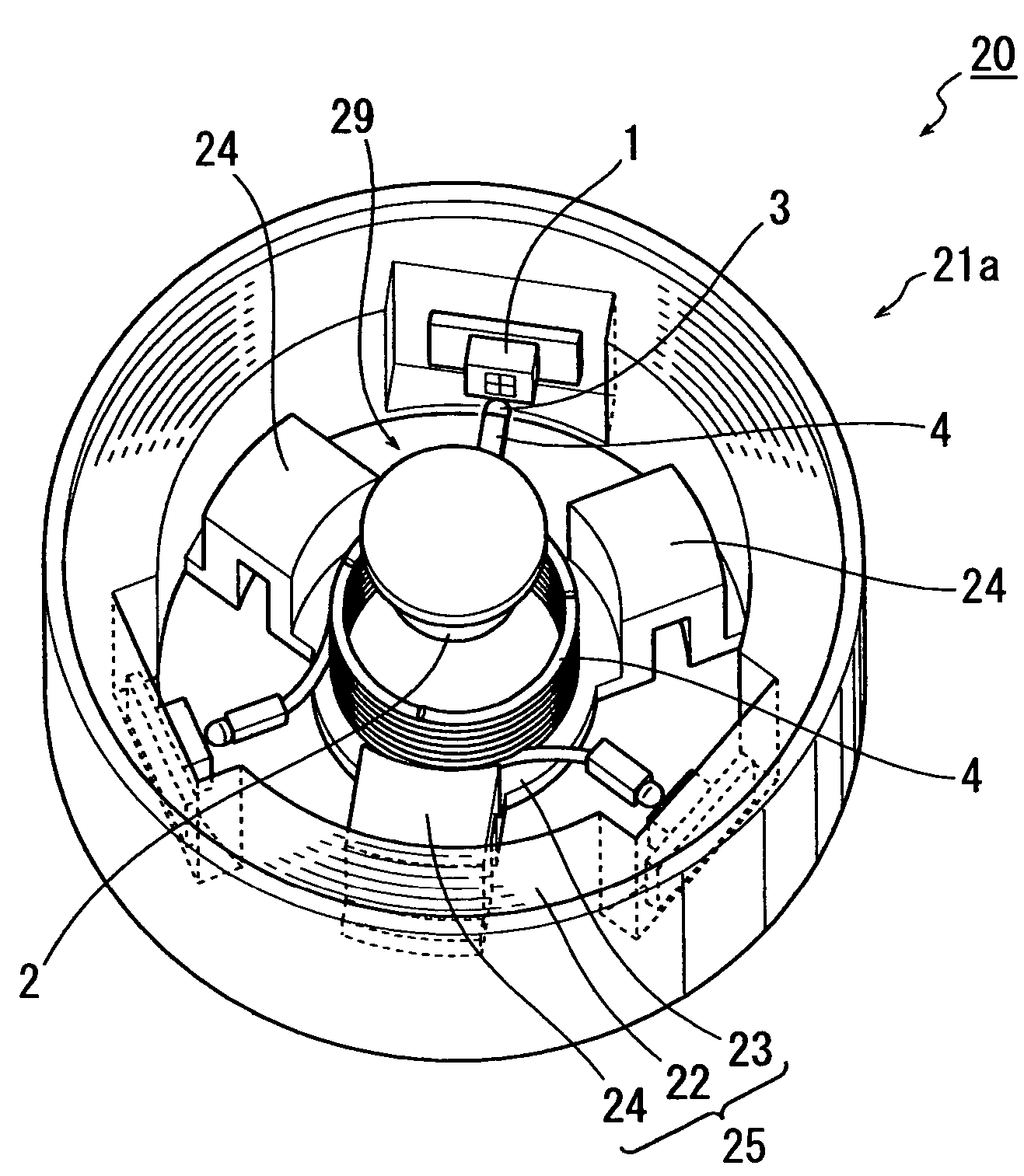
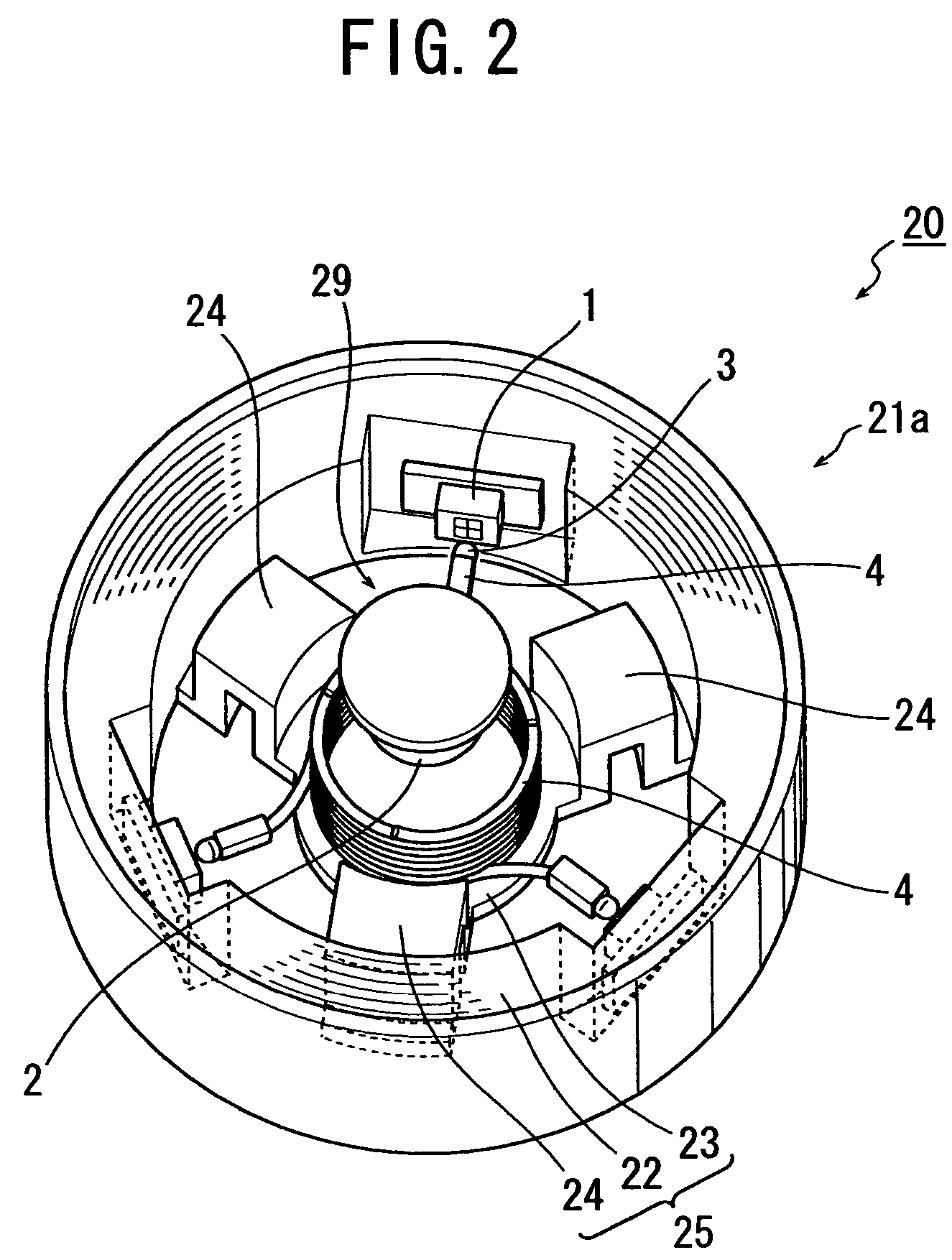
[0035]Referring to FIGS. 2 and 3 showing respectively perspective and top plan views of the six-axis force sensor 20 with the top lid 21b removed, the main body 21a is basically constituted by a frame 25 which integrally includes: a static member 22 with a hollow-circular cylindrical structure; an active member 23 disp...


PUM

PropertyMeasurementUnit
core diameteraaaaaaaaaa
distanceaaaaaaaaaa
outer circumferenceaaaaaaaaaa

Abstract

An optical displacement sensor structure includes a plurality of light receiving elements and a plurality of optical fibers together with one light source, wherein light emitted from the one light source is efficiently introduced into the plurality of optical fibers from the circumferences of the optical fibers, well kept inside the optical fibers while transmitting therethrough, and exits out from the end face of one end portion of each optical fiber so as to impinge on each light receiving element. This structure, with only one light source, provides a plurality of optical displacement sensors thus reducing power consumption without suffering a problem of light loss and successfully enables downsizing.

Description

PRIORITY TO BE CLAIMED[0001]This application claims priority from Japanese Patent Application No. 2005-319872, filed Nov. 2, 2005.BACKGROUND OF THE INVENTION[0002]1. Field of the Invention[0003]The present invention relates to an optical displacement sensor and an external force detecting device, and more particularly to an optical displacement sensor to sense a relative positional displacement between a reference segment and a measurement segment according to the displacement of the position of light received, and an external force detecting device to detect an external force applied to the measurement segment according to the output of the optical displacement sensor.[0004]2. Description of the Related Art[0005]An external force detecting device, such as an optical six-axis force sensor, has been conventionally known, in which a positional displacement of a force receiving member (i.e., measurement segment) to receive an external force applied relative to a static member (i.e., re...

Claims


Application Information

Patent Timeline
Patent Type & Authority Patents(United States)
IPC IPC(8): G01N21/86G01J1/04
CPCG01L5/166
Inventor KITAMURA, ATSUSHITANABE, SAWASUZUKI, SHINYA
Owner MINEBEA CO LTD
Why Eureka
Try Eureka