Optical disk recording apparatus controllable by table of multi-pulse patterns

a multi-pulse pattern, optical disk technology, applied in the direction of recording signal processing, digital signal error detection/correction, instruments, etc., can solve the problems of failure to form pits, poor pits cannot be formed, and the pulse train cannot allow the formation of pits having the correct length, etc., to achieve good record quality

Active Publication Date: 2009-02-17
YAMAHA CORP
View PDF17 Cites 12 Cited by
  • Summary
  • Abstract
  • Description
  • Claims
  • Application Information

AI Technical Summary

Benefits of technology

[0019]In this invention, heating and rapid cooling are repeated by intermittently applying a laser light shorter than a pit to be formed as a multi-pulse, thereby forming pits having a predetermined length on the recording surface of the optical disk. A pulse width which is a heating period for applying the laser light with write power and a pulse interval which is a cooling period for turning off the laser light with bottom power are combined to determine a multi-pulse pattern in which pits having a desired length are formed for each pit length (3T to 11T in the case of EFM of a CD), thereby forming a multi-pulse pattern table. A plurality of multi-pulse pattern tables each having different patterns is produced and stored in the storage section. When pits are formed on an optical disk, that is, when information is recorded, one is selected from the above plurality of multi-pulse pattern tables on the basis of one or both conditions: a kind of optical disk, and a recording speed at which information is recorded on this optical disk. This mean

Problems solved by technology

The recording layer is heated by applying a laser light, but in this case, there exists a disadvantage that, during writing, the rapid cooling is not satisfactorily achieved when a high power (write power) laser light is continuously applied and the recording layer that has been made amorphous once is turned again to the crystalline state, resulting in failure to form the pits.
Therefore, when the write strategy for 1T multi-pulse is performed at 24 times speed to raise a pulse of 0.5T width, the pulse finishes before laser power rises as shown in FIG. 7(B), which thus causes a problem

Method used


Image

  • Optical disk recording apparatus controllable by table of multi-pulse patterns
  • Optical disk recording apparatus controllable by table of multi-pulse patterns
  • Optical disk recording apparatus controllable by table of multi-pulse patterns

Examples


Embodiment Construction

[0028]An optical disk recording apparatus in accordance with an embodiment of this invention will be described in reference to the drawings. A CD-RW drive which writes and erases data in and from a CD-RW will be described as an example in this embodiment.

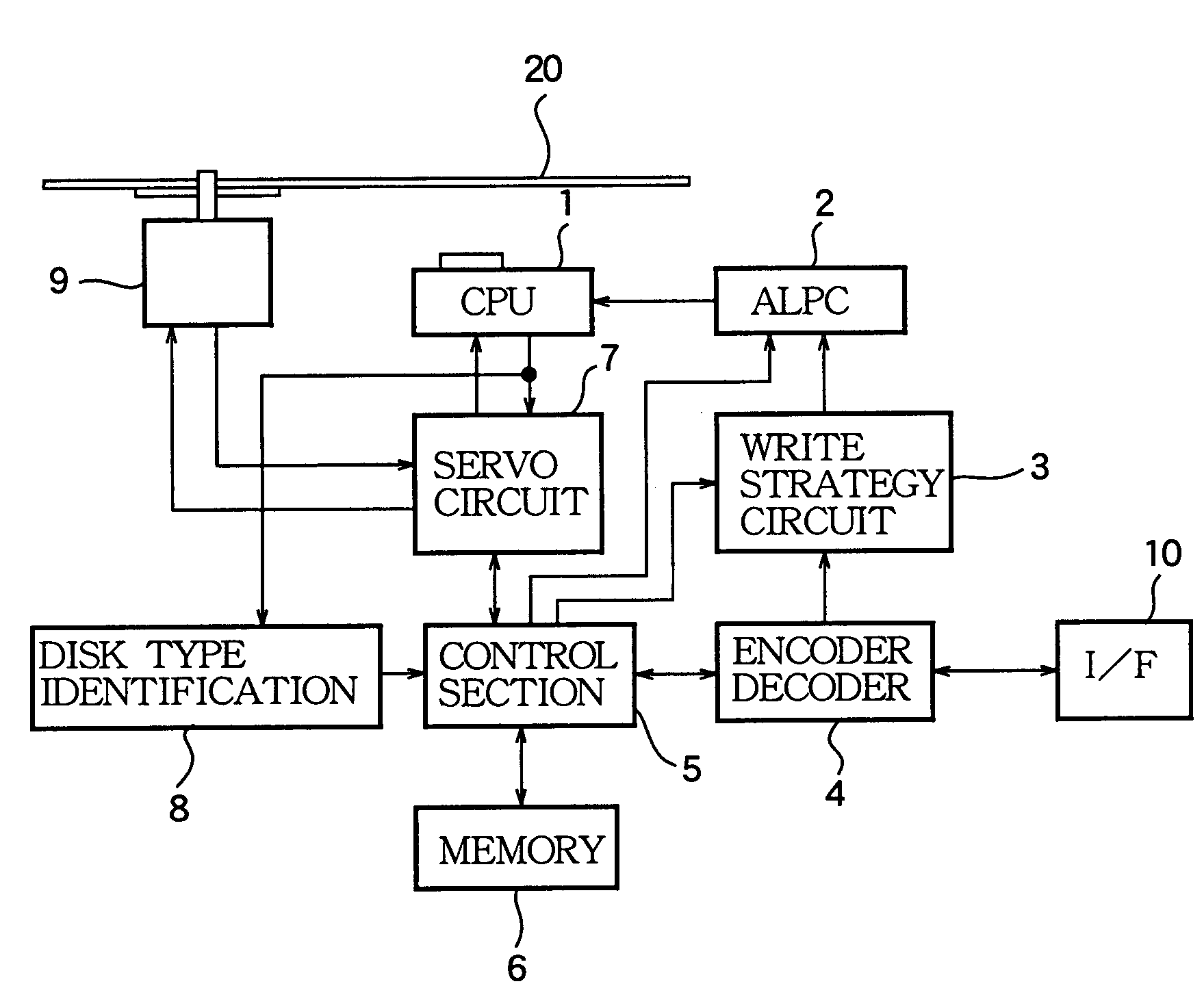
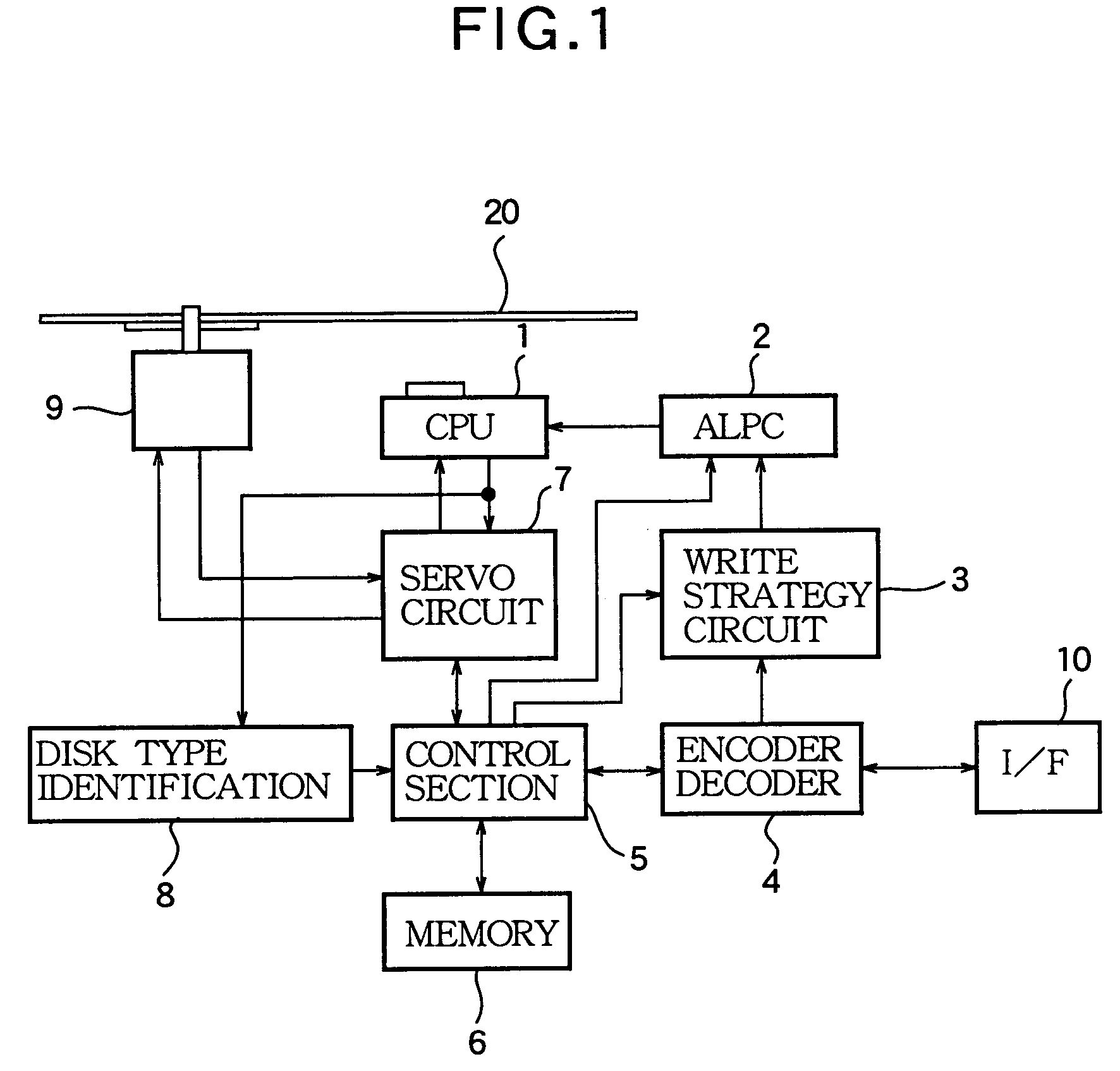
[0029]FIG. 1 is a schematic block diagram of the CD-RW drive. A disk 20, which is a CD-RW, is rotated at a predetermined rotation speed by a spindle motor 9. An optical system 1 faces a recording surface of the disk 20. The optical system 1 has a built-in semiconductor laser. This semiconductor laser emits light with predetermined power and in a predetermined multi-pulse pattern under the control of an ALPC (Automatic Laser Power Controller) 2, a write strategy circuit 3 and an encoder / decoder 4, and irradiates the recording surface of the disk 20 with the pulsed laser light.

[0030]A servo control circuit 7 controls the rotation speed of the spindle motor 9, a position in a radial direction of the disk of the optical system 1, and a ...


PUM


Abstract

An optical disk recording apparatus is designed for forming pits on a recording surface of an optical disk of a given type at a given recording speed by applying a laser light in the form of a sequence of multiple pulses obtained by intermittently turning on and off the laser light according to a given multi-pulse pattern. In the apparatus, a write strategy circuit is set with a pattern table and controls the turning on and off of the laser light according to a multi-pulse pattern selected from the pattern table in correspondence to a length of the pit to be formed. A storage section stores a plurality of pattern tables of different kinds, each pattern table containing a plurality of multi-pulse patterns corresponding to a plurality of lengths of the pit. A control section selects one of the pattern tables based on either of the recording speed and the type of the optical disk, and reads out the selected pattern table from the storage section and sets the read pattern table in the write strategy circuit.

Description

BACKGROUND OF THE INVENTION[0001]1. Technical Field of the Invention[0002]The present invention relates to an optical disk recording apparatus and, more particularly, to an improvement of write control (write strategy) of a CD-RW drive.[0003]2. Prior Art[0004]In a CD-RW, a phase-transition material is used for a recording layer, and when heated and then rapidly cooled, the phase-transition material is phase-changed from a crystalline state to an amorphous state to form pits. In addition, when the phase-transition material is heated and gradually cooled, the pits phase-changed into the amorphous state are returned to the crystalline state to thereby accomplish erasing of pits.[0005]The crystalline and amorphous states are different in reflectivity by about 15 percent, which thus enables record / erase of information in the form of pits.[0006]The recording layer is heated by applying a laser light, but in this case, there exists a disadvantage that, during writing, the rapid cooling is ...

Claims


Application Information

Patent Timeline
IPC IPC(8): G11B15/52G11B7/006
CPCG11B7/0062
Inventor OSAKABE, KATSUICHI
Owner YAMAHA CORP
Why Eureka
Try Eureka