
Method and apparatus for simulating quasi-periodic circuit operating conditions using a mixed frequency/time algorithm

a mixed frequency/time algorithm and quasi-periodic circuit technology, applied in the field of analog circuit design simulations, can solve the problems of analog circuit simulation further complicated, many circuits cannot be analyzed with periodic operation, and the analysis of analysis is the most difficult challenge in analog circuit stimulation

Inactive Publication Date: 2009-02-17
CADENCE DESIGN SYST INC
View PDF6 Cites 13 Cited by
  • Summary
  • Abstract
  • Description
  • Claims
  • Application Information

AI Technical Summary

Problems solved by technology

One of the most difficult challenges in analog circuit stimulation is the analysis of the circuits that operate on multiple time scales.
However, many circuits cannot be analyzed with the periodic-operating-point-plus-small-signal approach, because the above-described assumption may not apply.
The analog circuit simulation is further complicated by the fact that many multi-timescale circuits have a response (again mixers and switched-capacitor filters are typical examples) that is highly nonlinear with respect to at least one of the exciting inputs, and so steady-state approaches, such as the multi-frequency harmonic balance approach, do not perform well.
Unfortunately, existing MFT algorithms suffer from several drawbacks that prevent their application to practical circuits, particularly large circuits.
In existing MFT algorithms, poor sample point selection leads to ill-conditioned simulation environment, in which simulation values may be unsolveable with acceptable accuracy.
However, the effectiveness of the M-PDE method to simulate large circuits has yet to be proven.
In addition, there is evidence that, for some circuits, the M-PDE method generates inaccurate simulation results.

Method used


Image

  • Method and apparatus for simulating quasi-periodic circuit operating conditions using a mixed frequency/time algorithm
  • Method and apparatus for simulating quasi-periodic circuit operating conditions using a mixed frequency/time algorithm
  • Method and apparatus for simulating quasi-periodic circuit operating conditions using a mixed frequency/time algorithm

Examples


Embodiment Construction

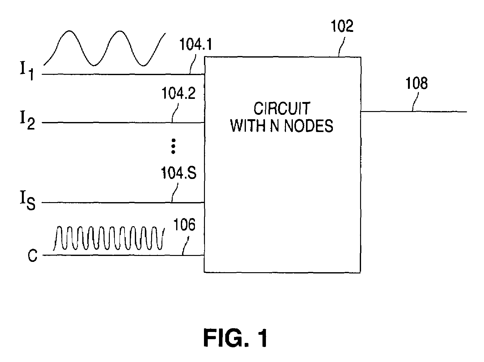
[0027]FIG. 1 shows circuit block 102 including N circuit nodes, which will be used to illustrate a simulation process in accordance with the present invention. Circuit 102 receives S information signals I1, I2, . . . , Is from inputs 104.1, 104.2, . . . , 104.s, respectively. Circuit 102 also receives a clock (or reference) signal C from input 106. In response to receipt of the input signals, circuit 102 generates a signal at output 108.

1. The Improved MFT Algorithm

[0028]The behavior of a circuit (such as circuit 102 in FIG. 1) can be described by a set of nonlinear differential-algebraic equations (DAEs) that can be written as

[0029]ⅆⅆt⁢Q⁡(v⁡(t))+I⁡(v⁡(t))+u⁡(t)=0,(1)

Where Q(v(t))∈N is typically the vector of sums of capacitor charges at each node, I(v(t))∈N is the vector of sums of resistive currents at each node, u(t)∈N is the vector of inputs, v(t)∈N is the vector of node voltages, and N is the number of circuit nodes.

[0030]The present invention is particularly advantageous in si...


PUM


Abstract

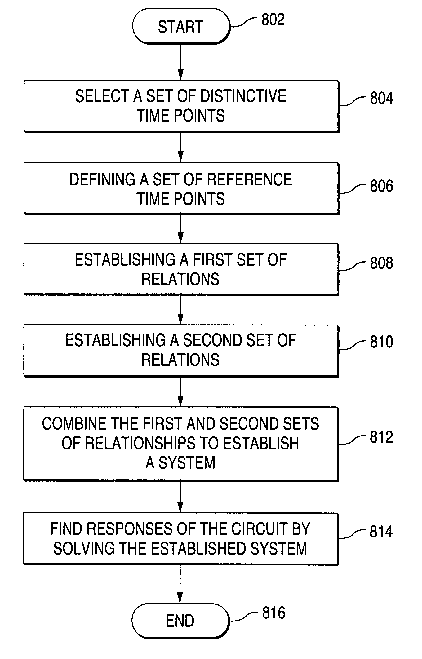
Described is a process for performing an improved mixed frequency-time algorithm to simulate responses of a circuit that receives a periodic sample signal and at least one information signal. The process selects a set of evenly spaced distinct time points and a set of reference time points. Each of the reference points is associated with a distinct time point, and a reference time point is a signal period away from its respective distinct time point. The process finds a first set of relationships between the values at the distinct time points and the values at the reference time points. The process also finds a second set of relationships between the values at the distinct time points and the values at the reference time points. The process then combines the first and second sets of relationships to establish a system of nonlinear equations in terms of the values at the distinct time points only. By solving the system of nonlinear equations, the process finds simulated responses of the circuit in time domain. The process then converts the simulated circuit responses from time domain to frequency domain.

Description

FIELD OF THE INVENTION[0001]The present invention relates generally to analog circuit design simulations, and more specifically to analog circuit design simulations using a mixed frequency / time approach.BACKGROUND OF THE INVENTION[0002]Using a description language such as a netlist and device models an analog circuit can be first designed in terms of its predetermined inputs and expected outputs. The analog circuit design is then simulated before it is physically fabricated on a silicon chip.[0003]One of the most difficult challenges in analog circuit stimulation is the analysis of the circuits that operate on multiple time scales. Typical examples of this type of circuits are switched-capacitor filters and circuits used in RF (radio frequency) communications systems. Applying standard transient analysis to a circuit of this type requires simulation of the detailed responses of the circuit over hundreds of thousands of clock cycles (millions of time points).[0004]Many circuits of en...

Claims


Application Information

Patent Timeline
IPC IPC(8): G06F17/10G06F17/50
CPCG06F17/5036G06F30/367
Inventor FENG, DANPHILLIPS, JOEL R.KUNDERT, KENNETH
Owner CADENCE DESIGN SYST INC
Learn More