RF payment via a mobile device

a mobile device and payment technology, applied in the field of transaction devices, can solve the problems of mobile phones and miniaturized portable personal computers such as pdas, which do little to address fraud issues associated with lost or stolen transaction cards, and are not visible in the field of smart cards

Inactive Publication Date: 2009-02-17
LIBERTY PEAK VENTURES LLC
View PDF452 Cites 94 Cited by
  • Summary
  • Abstract
  • Description
  • Claims
  • Application Information

AI Technical Summary

Benefits of technology

[0012]It is, therefore, an object of the present invention to provide a RF operable transaction device manufacturing system and method which requires little retrofitting of conventional transaction card manufacturing and personalization machinery.
[0020]In another embodiment, the transaction device may not be removed from the transporter. Instead, the transaction device combination may be left intact. The combination may be used to complete a RF transaction since the RF module is included in the transaction device (which is included in the transaction device combination). In this way, the transaction device combination may be used in similar manner as a conventional RF transaction device to complete a transaction. That is, a user may position the transaction device combination in proximity to a RFID reader. The RF module may then provide transaction device account information (e.g., account number, user identifier, device identifier) to the reader, which may forward the information to a merchant system or POS for transaction completion.

Problems solved by technology

As the number of issued transaction cards increases, so do the security issues surrounding transaction card transactions.
While smart cards enhanced some security surrounding transaction devices, smart cards did little to address fraud issues associated with a lost or stolen transaction card.
The RF transaction device may be attached to the personal article in an unobtrusive manner because of its smaller size.
Both mobile telephones and miniaturized portable personal computers, such as PDAs, suffer from one drawback in that they are generally not configured for use in any other way than originally intended.

Method used


Image

  • RF payment via a mobile device
  • RF payment via a mobile device
  • RF payment via a mobile device

Examples


Embodiment Construction

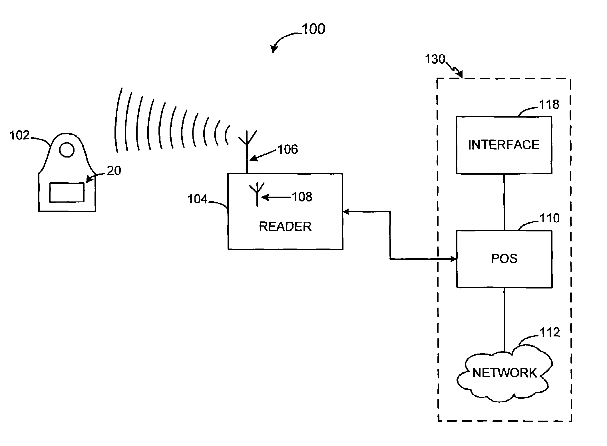
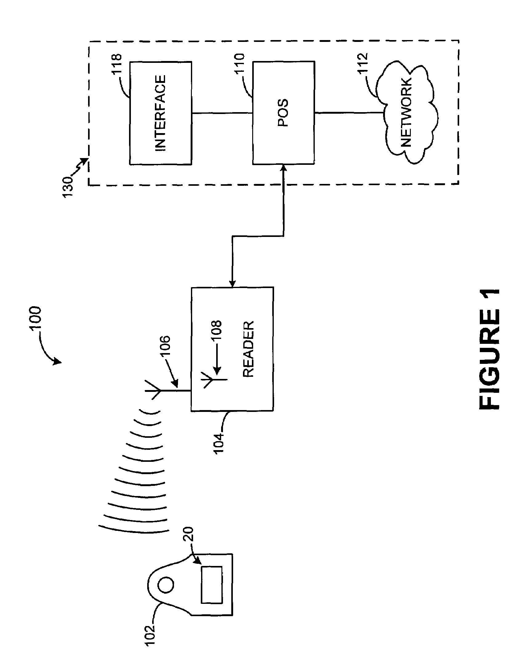
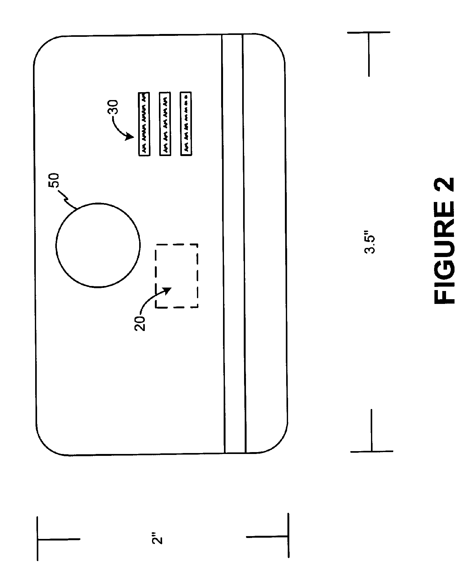
[0053]The present invention relates to contactless transaction devices and methods of making and using the same. Specifically, the present invention relates to a system and method for providing a RF transaction device using conventional transaction card manufacturing procedures. The present invention addresses the shortcomings in the prior art by providing a cost effective method for manufacturing irregular shaped RF transaction devices.

[0054]The present invention may be described herein in terms of functional block components, screen shots, optional selections and various processing steps. Such functional blocks may be realized by any number of hardware and / or software components configured to perform to specified functions. For example, the present invention may employ various integrated circuit components (e.g., memory elements, processing elements, logic elements, look-up tables, and the like), which may carry out a variety of functions under the control of one or more microproc...


PUM


Abstract

A process for providing an RF module configured to convert a nontraditional transaction device for traditional transaction completion is disclosed. The RF module is placed in physical and logical communication with a microprocessor of a nontraditional transaction device for providing user account information to the microprocessor and for receiving data from a RFID reader, kiosk or personal computer. The microprocessor is configured to activate operation of the RF module prior to transaction processing. The RF module may also receive secondary identification information, such as, a PIN, voice recognition data or biometric data for secondary end user authentication. The RF module may also transmit user account data for transaction processing using a USB interface of the nontraditional transaction device.

Description

CROSS-REFERENCE TO RELATED APPLICATIONS[0001]This invention ('965 application) is a non-provisional of U.S. Provisional Application No. 60 / 512,297, filed Oct. 17, 2003. The '965 application is also a continuation of U.S. patent application Ser. No. 10 / 746,781, entitled “A SYSTEM AND METHOD FOR MANUFACTURING A PUNCH-OUT RF TRANSACTION DEVICE,” filed Dec. 24, 2003. The '781 application is also a continuation-in-part of U.S. patent application Ser. No. 10 / 340,352, entitled “SYSTEM AND METHOD FOR INCENTING PAYMENT USING RADIO FREQUENCY IDENTIFCATION IN CONTACT AND CONTACTLESS TRANSACTIONS,” filed Jan. 10, 2003. The '352 application is a non-provisional of U.S. Provisional Application No. 60 / 396,577, filed Jul. 16, 2002.The '352 application is a continuation in part of U.S. patent application Ser. No. 10 / 192,488, entitled “SYSTEM AND METHOD FOR PAYMENT USING RADIO FREQUENCY IDENTIFICATION IN CONTACT AND CONTACTLESS TRANSACTIONS,” filed Jul. 9, 2002, now U.S. Pat. No. 7,239,226 issued on ...

Claims


Application Information

Patent Timeline
Patent Type & Authority Patents(United States)
IPC IPC(8): H04L9/00
CPCG06K19/07749G06Q20/32G06Q20/3226G06Q20/325G06Q20/3278G06Q20/341G06Q20/347G06Q20/382G06Q20/40G06Q20/4014G06Q30/06G07F7/08G07F7/0833G07F7/0886G07F7/10G07F7/1008G07F7/1075
Inventor BISHIP, FREDSAUNDERS, PETER D
Owner LIBERTY PEAK VENTURES LLC
Why Eureka
Try Eureka