Vibratory gyroscope with parasitic mode damping

a vibration gyroscope and parasitic mode technology, applied in the field of gyroscopes, can solve the problems of large and heavy, large and heavy, and old mechanical gyroscopes with very heavy mechanisms

Active Publication Date: 2009-02-24
THE BOEING CO
View PDF6 Cites 14 Cited by
  • Summary
  • Abstract
  • Description
  • Claims
  • Application Information

AI Technical Summary

Benefits of technology

[0059]Employing the in-plane design described, embodiments of the present invention obtain many advantages over other out-of-plane gyros. For example, the central support bond carries no vibratory loads, eliminating any friction possibility or anchor loss variability. In addition, simultaneous photolithographic machining of the resonator and electrodes is achieved via the slots. Furthermore, diametral electrode capacitances can be summed to eliminate vibration rectification and axial vibration does not change capacitance to a first order. Modal symmetry is also largely determined by photolithographic symmetry not wafer thickness as with other designs. Isolation and optimization of sense capacitance (e.g., from the outer slots) and drive capacitance (e.g., from the inner slots) is achieved. Embodiments of the invention also achieve a geometric scalable design to smaller or larger diameters and thinner or thicker wafers. In addition, embodiments of the invention can be entirely defined by slots of the same width for machining uniformity and symmetry. Implementation of the present invention can also accommodate silicon anisotropy producing frequency splits. For example, a <111> silicon wafer and / or a varied slot width can be used.

Problems solved by technology

Older conventional mechanical gyroscopes were very heavy mechanisms by current standards, employing relatively large spinning masses.
Currently this is often performed with expensive conventional spinning mass gyros (e.g., a Kearfott inertial reference unit) or conventionally-machined vibratory gyroscopes (e.g. a Litton hemispherical resonator gyroscope inertial reference unit).
However, both of these are very expensive, large and heavy.
This transfer or coupling admits external disturbances and energy loss indistinguishable from inertial rate input and hence leads to sensing errors and drift.
Other planar tuning fork gyroscopes may achieve a degree of isolation of the vibration from the baseplate, however these gyroscopes lack the vibrational symmetry desirable for tuned operation.
However, these designs are not suitable for or have significant limitations with thin planar silicon microfabrication.
However its high aspect ratio and three-dimensional curved geometry is unsuitable for inexpensive thin planar silicon microfabrication.
Moreover, the case for this gyroscope is not of the same material as the resonator proof mass so that the alignment of the pickoffs and torquers relative to the resonator proof mass change with temperature, resulting in gyroscope drift.
However such increased isolation comes at the expense of proportionately heavier seismic mass and / or lower support frequency.
Both effects are undesirable for compact tactical inertial measurement unit (IMU) applications because of proof mass misalignment under acceleration conditions.
Furthermore, the scale of previous silicon microgyroscopes (e.g., U.S. Pat. No. 5,894,090) can not been optimized for navigation or pointing performance resulting in higher noise and drift than desired.
This problem stems from dependence on out of plane bending of thin epitaxially grown silicon flexures to define critical vibration frequencies that are limited to 0.1% thickness accuracy.
Consequently device sizes are limited to a few millimeters.
Such designs exhibit high drift due to vibrational asymmetry or unbalance and high rate noise due to lower mass which increases thermal mechanical noise and lower capacitance sensor area which increases rate errors due to sensor electronics noise.
Scaling up of non-isolated silicon microgyros is also problematic because external energy losses will increase with no improvement in resonator Q and no reduction in case-sensitive drift.
Conventionally machined navigation grade resonators such as quartz hemispherical or shell gyros have the optimum noise and drift performance at large scale, e.g. 30 mm and three-dimensional manufacturing precision, however such gyros are expensive and slow to manufacture.
Micromachined silicon vibratory gyroscopes have lower losses and better drift performance at smaller scale but pickoff noise increases and mechanical precision decreases at smaller scale so there are limits to scaling down with conventional silicon designs.
However this process is not suitable for microgyros with narrow mechanical gaps and has limited resolution, necessitating larger electrostatic bias adjustments in the final tuning process.

Method used


Image

  • Vibratory gyroscope with parasitic mode damping
  • Vibratory gyroscope with parasitic mode damping
  • Vibratory gyroscope with parasitic mode damping

Examples


Embodiment Construction

[0042]1. Overview

[0043]In the following description of the preferred embodiment, reference is made to the accompanying drawings which form a part hereof, and in which is shown by way of illustration a specific embodiment in which the invention may be practiced. It is to be understood that other embodiments may be utilized and structural changes may be made without departing from the scope of the present invention.

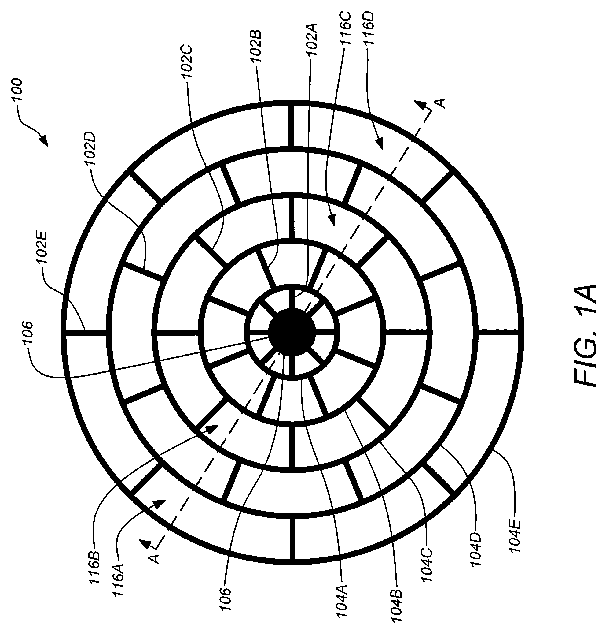
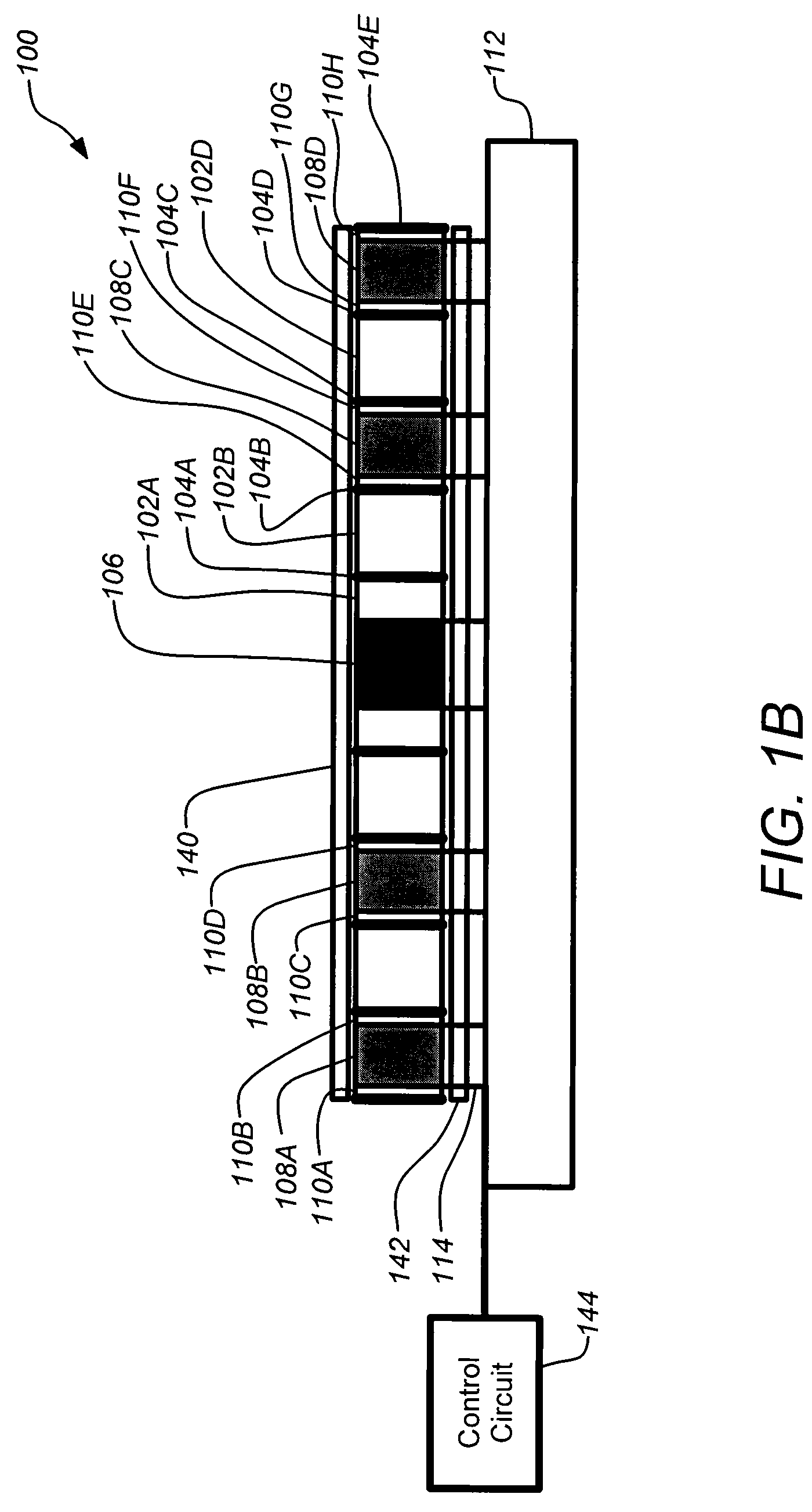
[0044]As previously described, embodiments of the present invention can be applied to a planar resonator supported on a central rigid stem and with substantially increased sensing capability by utilizing a short solid cylindrical resonator or disc having a substantial useable internal resonator volume, allowing the incorporation of significantly more sensing for the measurement of desirable resonator internal motion. This use of a planar element, such as a disc, rather than a shell or ring results in substantial top and bottom surface areas and a large internal volume for m...


PUM


Abstract

Operation of a planar resonator gyroscope with in-plane parasitic modes of vibration to obtain improved performance is disclosed. A planar resonator gyroscope, such as a disc resonator gyroscope, may be operated with embedded electrodes. The embedded electrodes may be disposed adjacent to the planar resonator and proximate to one or more anti-nodes of a parasitic vibration mode. A sensed amplitude of the parasitic mode is applied in differential signals used to operate the gyroscope. A feedback controller for damping the parasitic mode applies a drive voltage generated from the proportional voltage to one or more drive electrodes adjacent to the planar resonator disposed proximate to one or more anti-nodes of the parasitic vibration mode of the planar resonator. Parasitic in-plane modes may be thus damped in operating the gyroscope with active damping applied through an analog operational amplifier or digital feedback.

Description

CROSS-REFERENCE TO RELATED APPLICATIONS[0001]This application is related to the following co-pending patent applications, which are both incorporated by reference herein:[0002]U.S. patent application Ser. No. 11 / 371,596, filed on Mar. 9, 2006, and entitled “ISOLATED PLANAR GYROSCOPE WITH INTERNAL RADIAL SENSING AND ACTUATION”, by Kirill V. Shcheglov et al., published as U.S. 2006 / 0162146A1; and[0003]U.S. patent application Ser. No. 11 / 199,004, filed Aug. 8, 2005, and entitled “INTEGRAL RESONATOR GYROSCOPE”, by Kirill V. Shcheglov et al., published as U.S. 2005 / 0274183A1.BACKGROUND OF THE INVENTION[0004]1. Field of the Invention[0005]The present invention relates to gyroscopes, and in particular to planar resonator gyroscopes or inertial sensors and their operation. More particularly, this invention relates to the control and damping of isolated planar resonator inertial sensors and gyroscopes.[0006]2. Description of the Related Art[0007]Mechanical gyroscopes are used to determine di...

Claims


Application Information

Patent Timeline
Patent Type & Authority Patents(United States)
IPC IPC(8): G01P9/04
CPCG01C19/5684G01P9/04G01C19/56
Inventor WHELAN, DAVIDCHALLONER, A. DORIAN
Owner THE BOEING CO
Why Eureka
Try Eureka