Gearbox brake for mining machinery

a gearbox and mining machinery technology, applied in mechanical equipment, axially engaging brakes, transportation and packaging, etc., can solve the problems of large size, difficult sealing, and loss of favor

Inactive Publication Date: 2009-02-24
PT TECH INC
View PDF15 Cites 30 Cited by
  • Summary
  • Abstract
  • Description
  • Claims
  • Application Information

AI Technical Summary

Benefits of technology

[0009]Yet a further aspect of the invention is the provision of a wet disc brake that can be adapted to replace existing gearboxes for underground mining machinery by employing the same mounting structures, but without adversely increasing the envelope of the gearbox and while providing ease of serviceability.
[0011]Still a further aspect of the invention is the provision of a wet disc brake for a gearbox of underground mining machinery and the method for implementing the same, which is reliable, durable, cost effective, and given to ease of service.

Problems solved by technology

However, dry caliper disc brakes are generally not preferred in rigorous mining conditions and they have also lost favor due to changes in governmental regulations.
While these brakes performed much better than the dry caliper brakes, they were large, complicated in design, difficult to seal, difficult to replace, costly, and with a torque setting that typically required modification to accommodate different gear ratios.
Heretofore, the art has been incapable of such packaging in a durable, reliable, and cost efficient manner.

Method used


Image

  • Gearbox brake for mining machinery
  • Gearbox brake for mining machinery
  • Gearbox brake for mining machinery

Examples


Embodiment Construction

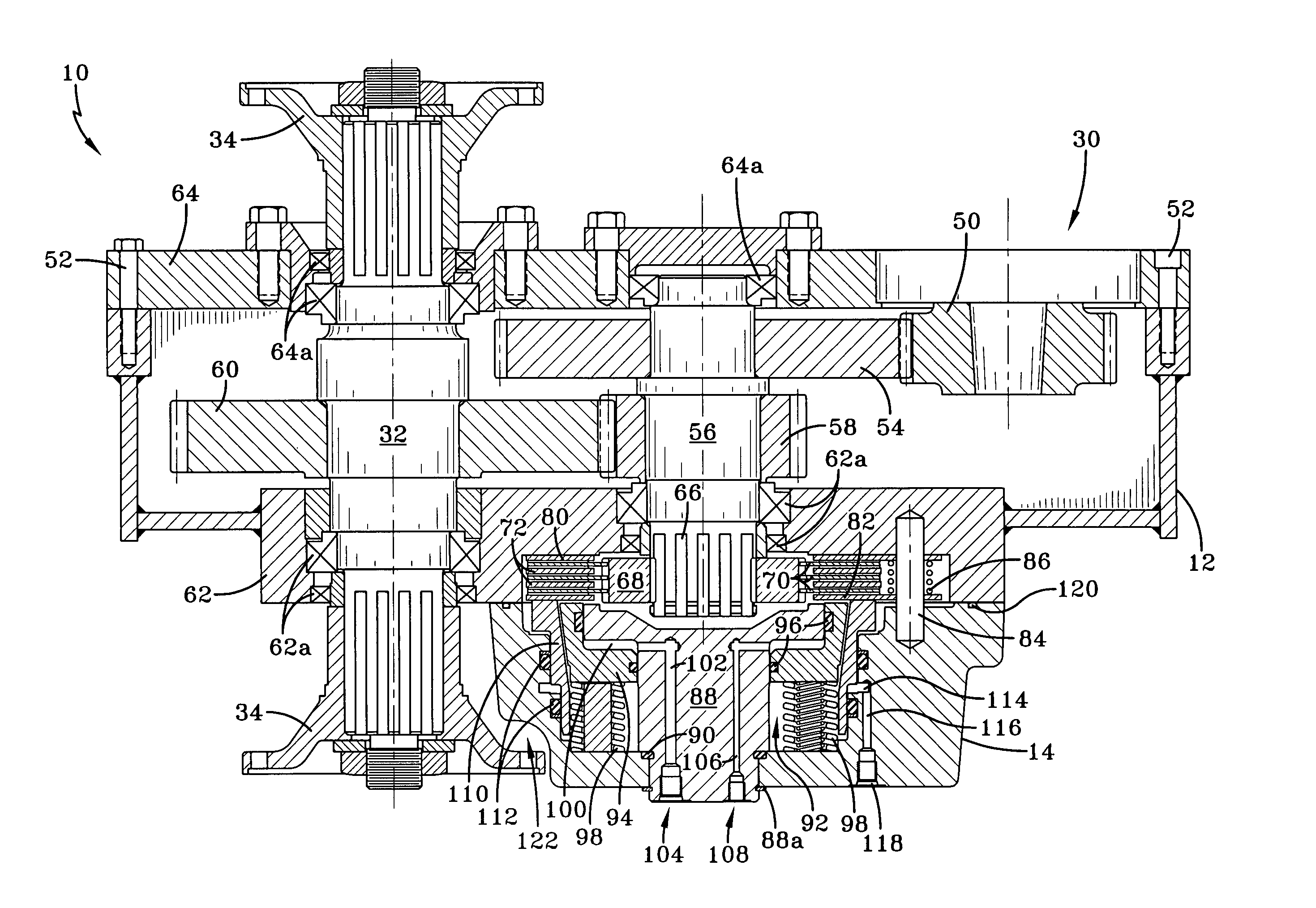
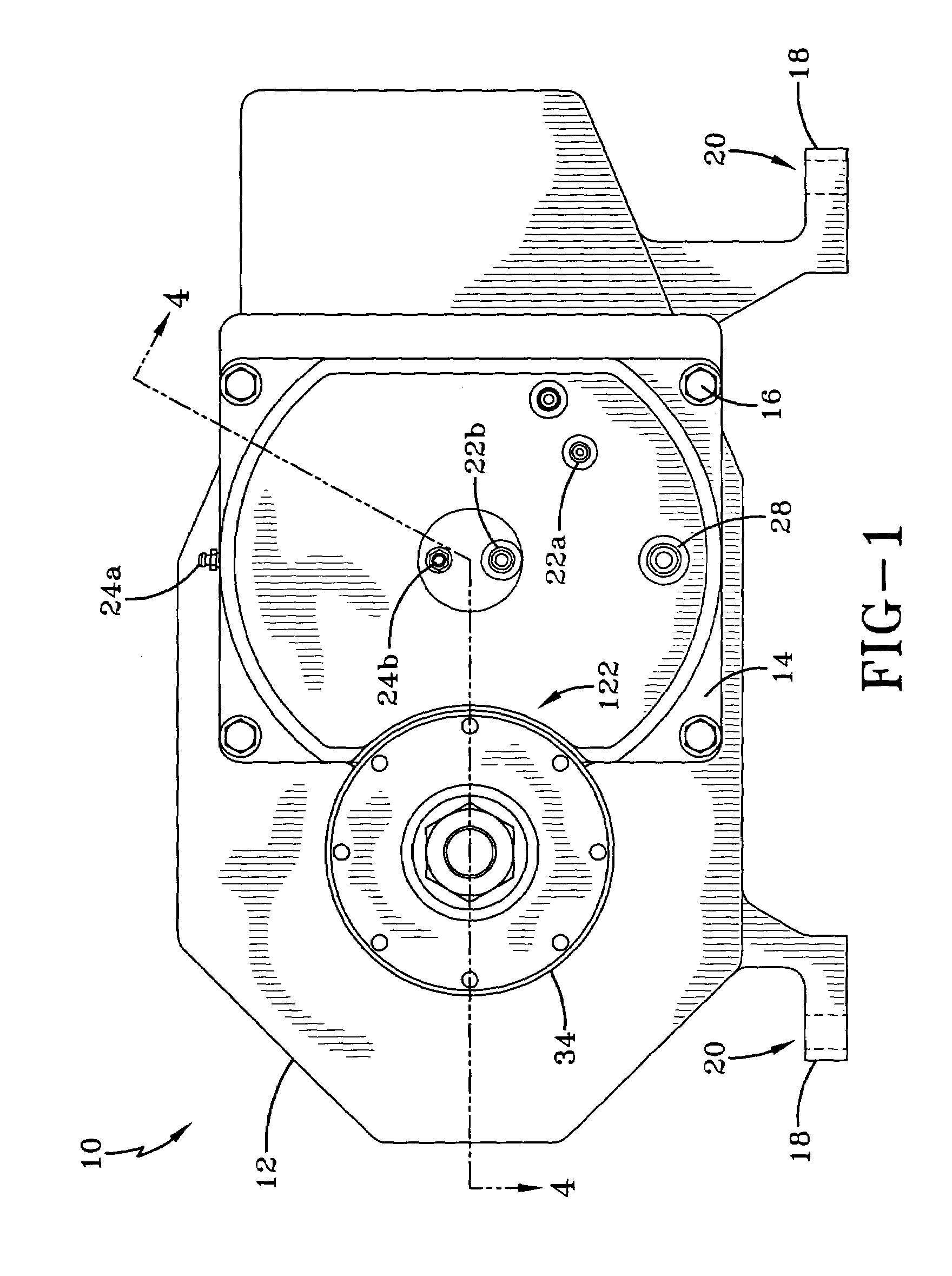
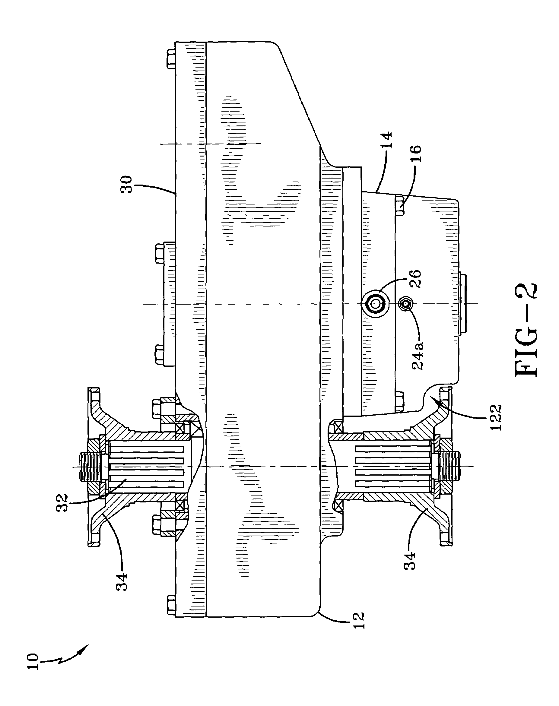
[0020]Referring now to the drawings and more particularly FIGS. 1 and 2, it can be seen that a gearbox and brake assembly made in accordance with the invention is designated generally by the numeral 10. The gear housing 12 is configured to receive a brake housing 14 attached thereto by bolts 16 or other appropriate means. The gearbox assembly is provided with a pair of feet or pads 18 for receipt of mating bolts through bores 20. The bores 20 are nominally 20.63 inches on centers, with the housing 12 having height of 16 inches measured from the bottom of the feet 18 to the top of the housing 12. The center lines of the output shaft and the intermediate shaft to which the brake assembly is attached lie along a center line nominally 9 inches from the bottom of the pad 18. This positioning and spacing is consistent with the prior art gearbox assembly to be replaced by the assembly 10.

[0021]As a portion of the instant invention, actuation port nipples 22a and 22b and bleeder port nipple...


PUM


Abstract

A gearbox having an integral wet brake assembly is provided to replace the prior gearbox assembly of an underground mining machine. The brake housing is configured and contoured to be nestingly received upon the gearbox housing and without intrusion upon the output drive flanges. The brake housing includes concentric parking and service brake pistons adapted to engage and disengage a brake disc stack provided within a cavity machined into an end plate of the gear box assembly. An intermediate shaft of the gearbox is provided with a hub to engage the rotary discs of the brake disc stack. The parking brake is normally engaged by a spring and released by hydraulic pressure, while the service brake is normally released by a spring and engaged by hydraulic pressure.

Description

TECHNICAL FIELD[0001]The invention herein resides in the art of power transmission devices and, more particularly, to a gearbox brake combination for use on underground mining machinery. Particularly, the invention relates to a wet brake adapted for use on the intermediate shaft of the gearbox having a two stage helical gear parallel shaft reduction. Specifically, the invention relates to a gearbox having a wet brake on the intermediate shaft and a method for adapting a wet brake to a gearbox for replacement of an existing gearbox.BACKGROUND OF THE INVENTION[0002]For nearly a half century, articulated four-wheel drive vehicles have been widely used in the underground mining industry. This type of vehicle configuration is common for scoops, shield haulers and the like. The front section of such vehicles contains a driven axle and the particular attachment (scoop, fork, etc.) and the rear section houses the drive system for the vehicle, its hydraulics, controls, batteries and the like...

Claims


Application Information

Patent Timeline
Patent Type & Authority Patents(United States)
IPC IPC(8): F16D55/02
CPCF16D55/38F16D59/02F16D65/186F16D65/853F16D2121/12F16D2121/14
Inventor ROGERS, RALPH F.
Owner PT TECH INC
Why Eureka
Try Eureka