Projector and processing line specification method

a technology of processing line and projector, applied in the field of projector, can solve the problems of inadequate and inaccurate keystone correction and other image processing operations, inaccurate identification of peak position in photographed images, and conventional methods, etc., and achieve the effect of adequate and accurate keystone correction

Inactive Publication Date: 2009-02-24
SEIKO EPSON CORP
View PDF7 Cites 18 Cited by
  • Summary
  • Abstract
  • Description
  • Claims
  • Application Information

AI Technical Summary

Benefits of technology

[0028]In a projector that is equipped with an imaging structure and a movable projection lens and photographs a projected image on a screen or another projection object with the imaging structure, the object of the invention is to eliminate the drawbacks of the prior art technique and to provide a technique of distinctly and accurately identifies the position of maximum brightness in the photographed image even under the condition of a shift of the projection lens.
[0034]The projector of this embodiment experimentally or otherwise determines a line passing through a position of maximum brightness in the photographed image corresponding to each detected shift level of the projection lens and stores a mapping of the positional information of the determined line to the shift level in the storage unit. Even under the condition of a shift of the projection lens, the control module specifies the line passing through the position of maximum brightness as the reference line corresponding to the detected shift level of the projection lens and thus accurately identifies the position of maximum brightness in the photographed image.
[0035]In the projector of this embodiment, the image processing unit adjusts the projected image, based on the image peak position identified by the control module. This arrangement enables adequate adjustment of the projected image based on the accurately identified image peak position, even under the condition of a shift of the projection lens.
[0036]In one preferable application of the projector of this embodiment, the image processing unit adjusts the projected image on the projection object to correct a distortion of the projected image caused by an inclination of the projector to the projection object.
[0037]Even in an inclined attitude of the projector to the projection object, the projector of this arrangement adjusts the projected image to correct a distortion of the projected image caused by the inclination of the projector, based on the accurately identified image peak position. Correction values for correcting the distortion of the projected image may be determined corresponding to the image peak position. This arrangement enables the distortion of the projected image to be corrected with the adequate correction values determined corresponding to the accurately identified image peak position. The projected image is thus adjustable to have significantly little distortion.
[0039]The intersection between the optical axis of the projector and the projection object may have the maximum brightness in the photographed image. In such cases, the above arrangement enables the control module to readily specify the line passing through the position of maximum brightness as the reference line.

Problems solved by technology

This conventional method, however, has some drawbacks due to the specification of the reference line.
This may result in inaccurate identification of the peak position in the photographed image and accordingly inadequate and inaccurate keystone correction and other image processing operations.

Method used


Image

  • Projector and processing line specification method
  • Projector and processing line specification method
  • Projector and processing line specification method

Examples


embodiment

A. Embodiment

A1. General Configuration of Projector

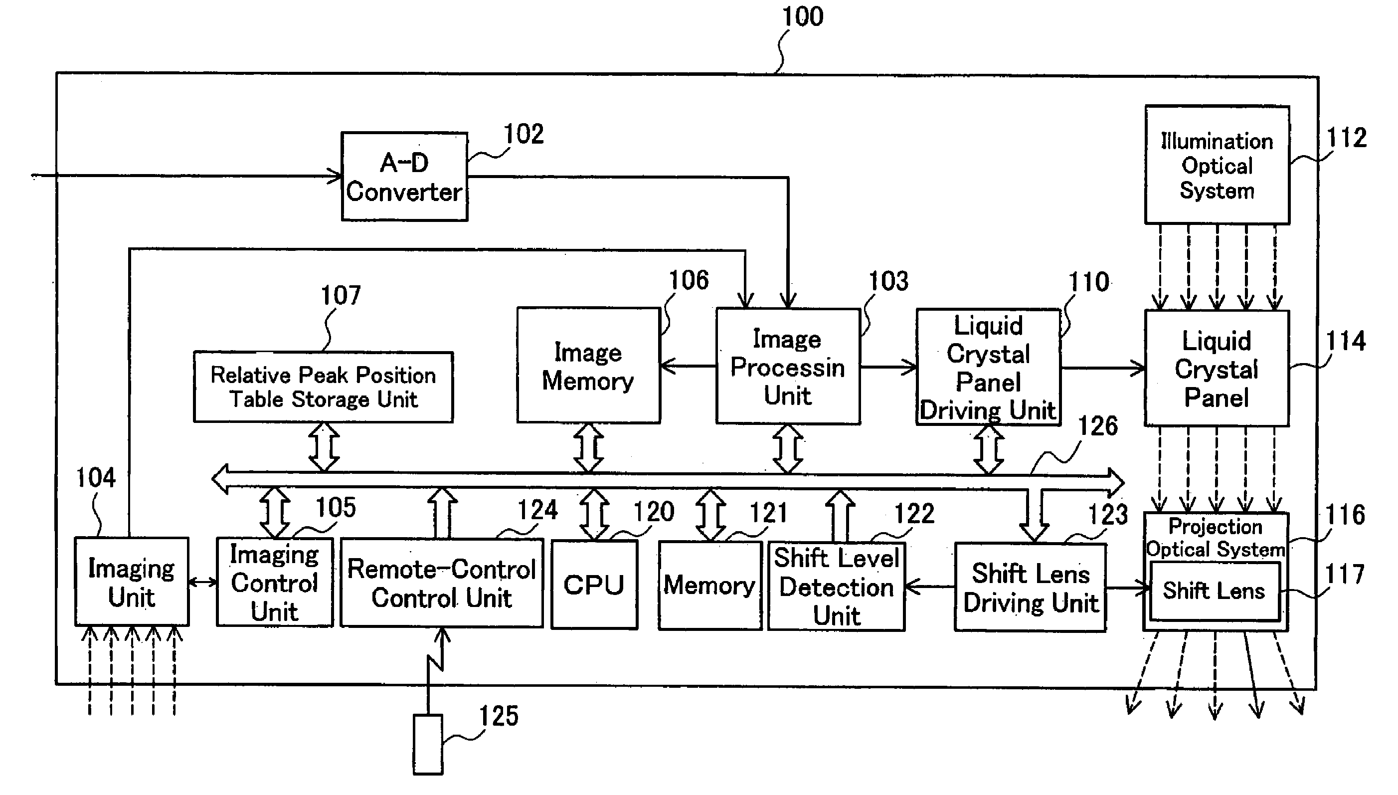
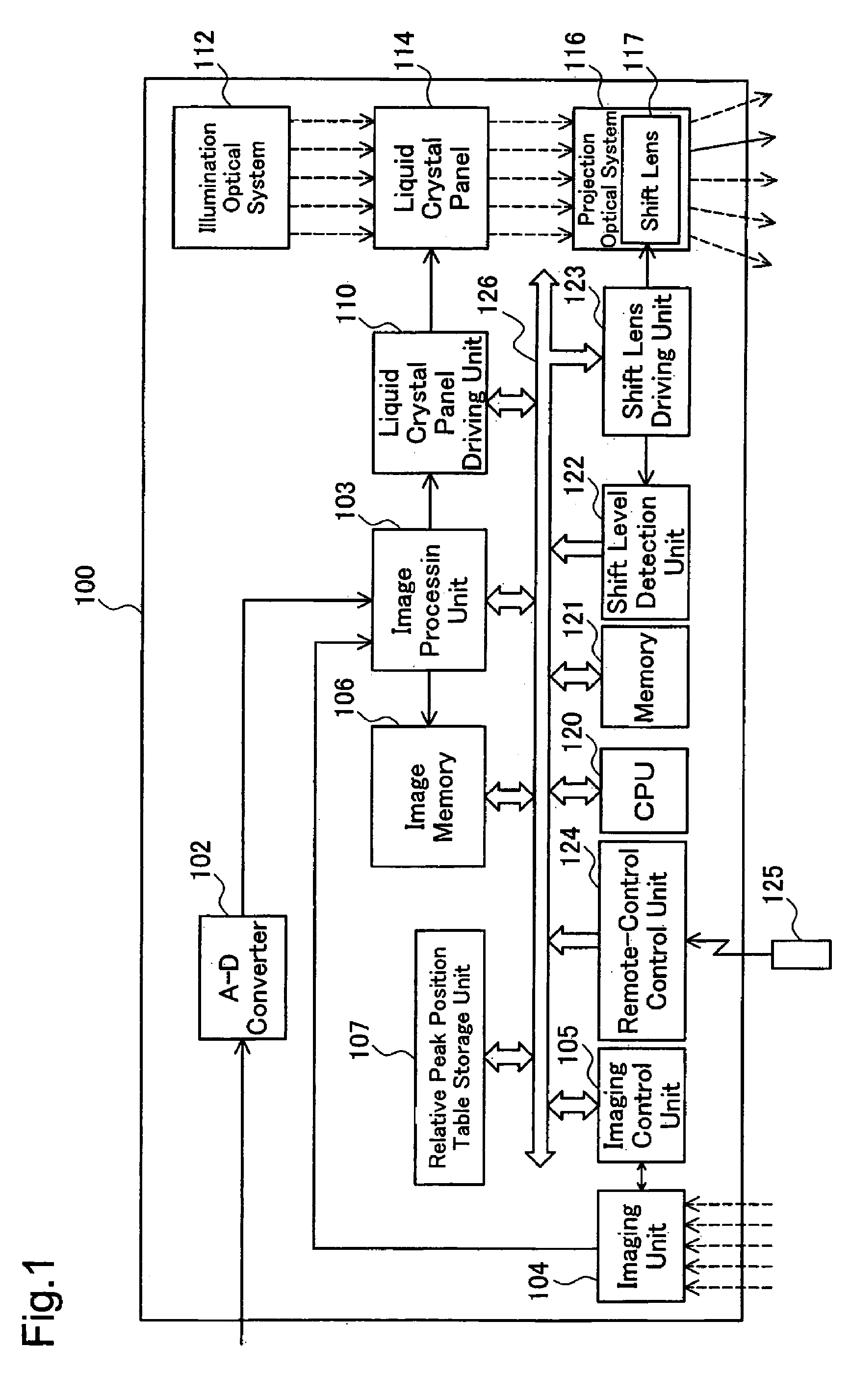
[0052]FIG. 1 schematically illustrates the configuration of a projector 100 in one embodiment of the invention. The projector 100 of this embodiment has the functions of photographing a projected image on a screen, identifying the position of maximum luminance in the photographed image, and making keystone correction, like the conventional projector PJ shown in FIGS. 5 and 6. The projector 100 of the embodiment determine a peak position on a specified horizontal line and accordingly identifies the position of maximum luminance in the photographed image, like the conventional projector PJ.

[0053]As illustrated, the projector 100 includes an A-D converter 102, an image processing unit 103, an imaging unit 104, an imaging control unit 105, an image memory 106, a relative peak position table storage unit 107, a liquid crystal panel driving unit 110, a CPU 120, a memory 121, a shift level detection unit 122, a shift lens driving unit 123,...

modified example 1

B1. Modified Example 1

[0099]In the structure of the embodiment, the projection orientation of the projector 100 is set to locate the optical axis point on the top side of a projected image at the bottommost position of the shift lens 117. Such projection orientation is, however, not restrictive. The projection orientation of the projector 100 may be set to locate the optical axis point above the top side of the projected image at the bottommost position of the shift lens 117.

[0100]In this modified arrangement, the optical axis point moves upward to become out of the projected image at a lower shift limit in the course of a downward shift of the shift lens 117. The relative peak position table accordingly has the relative peak position ‘100’ set corresponding to all the shift levels of and below the lower shift limit that locates the optical axis point on the top side of the projected image. Even when the optical axis point is out of the projected image, a horizontal line that is clo...

modified example 2

B2. Modified Example 2

[0102]In the relative peak position table used in the projector 100 of the embodiment, the highest relative peak position ‘100’ is set corresponding to the shift level ‘−100’ representing a shift to the bottommost position. The relative peak position corresponding to the shift level ‘−100’ may be slightly lower than the highest relative peak position ‘100’, for example, ‘99’ or ‘98’.

[0103]Under the condition of the shift level ‘−100’, the projection orientation of the projector 100 is set to locate the optical axis point on the top side of the projected image. The top side of the projected image forms a boundary between the bright projected image area and the dark non-projection area in the photographed image. The detected luminance values of the pixels on the top side of the projected image may be lower than the actual level due to the low luminance values of the adjoining darker area. This may cause difficulty in accurate identification of the position of max...


PUM


Abstract

A projector of the invention includes: a projection lens that is movable in a direction substantially perpendicular to an optical axis to project and display an image on a projection object; an imaging structure that photographs an area including at least the projected image on the projection object to take a photographed image; a shift level detection unit that detects a shift level of the projection lens; a control module that specifies a reference line to be processed in the photographed image; and a storage unit that stores a map of positional information to each shift level, where the positional information represents an expected relative line position to the projected image included in the photographed image. The control module specifies a display position of the projected image included in the photographed image, reads the positional information corresponding to the shift level detected by the shift level detection unit from the map stored in the storage unit, and specifies the reference line, based on the expected relative line position represented by the read positional information and the specified display position of the projected image. Even under the condition of a shift of the projection lens, the projector of this arrangement distinctly identifies the position of maximum brightness in the photographed image and thereby ensures accurate and adequate keystone correction and other required image processing operations.

Description

BACKGROUND OF THE INVENTION[0001]1. Field of the Invention[0002]The present invention relates to a projector that is equipped with a shift projection lens and an imaging unit and functions to project an image on a screen or another projection object and photograph the projected image with the imaging unit.[0003]2. Description of the Related Art[0004]Various projectors equipped with an imaging unit including a CCD (Charge Coupled Device) camera have been proposed to photograph a selected image projected on a screen or another projection object with the imaging unit and to adjust the zoom and the focus and correct a trapezoidal distortion of the projected image (keystone correction) based on the photographed image.[0005]One of such projectors is disclosed in Japanese Patent Laid-Open Gazette No. 2004-312690. This prior art projector analyzes a photographed image, identifies the position of maximum brightness in the photographed image, and makes keystone correction according to the ide...

Claims


Application Information

Patent Timeline
Patent Type & Authority Patents(United States)
IPC IPC(8): G03B21/00G03B21/14G03B3/00
CPCG09G3/002H04N9/3185H04N9/3194G09G2360/145
Inventor MIYASAKA, NORIAKI
Owner SEIKO EPSON CORP
Why Eureka
Try Eureka