
Foreign object damage resistant vane assembly

a technology for foreign objects and vanes, applied in the direction of machines/engines, liquid fuel engines, combustion air/fuel air treatment, etc., can solve the problems of affecting the performance of the engine, cutting the grommet and damage to other surrounding components,

Active Publication Date: 2009-02-24
PRATT & WHITNEY CANADA CORP
View PDF22 Cites 16 Cited by
  • Summary
  • Abstract
  • Description
  • Claims
  • Application Information

AI Technical Summary

Benefits of technology

The vane assembly effectively restricts vane tip movement during foreign object impacts, reduces grommet damage, simplifies installation, and improves airflow smoothness by eliminating the need for adhesives, thereby enhancing engine performance and reducing maintenance complexity.

Problems solved by technology

However, during a foreign object damage event a vane which is hit will move rearward as a result of the impact, and the vane edge, which tends to be sharp, can cause cutting of the grommet and damage to other surrounding components.
Also, the airflow surrounding the grommets often produces a force which tends to lift and displace the grommets, thus requiring the use of adhesive or other similar measures to ensure that they stay in place.
Such a use of adhesive complicates the installation and replacement of vanes.
Moreover, the protruding grommets can disturb the airflow, which can alter the engine's performance.

Method used


Image

  • Foreign object damage resistant vane assembly
  • Foreign object damage resistant vane assembly
  • Foreign object damage resistant vane assembly

Examples


Embodiment Construction

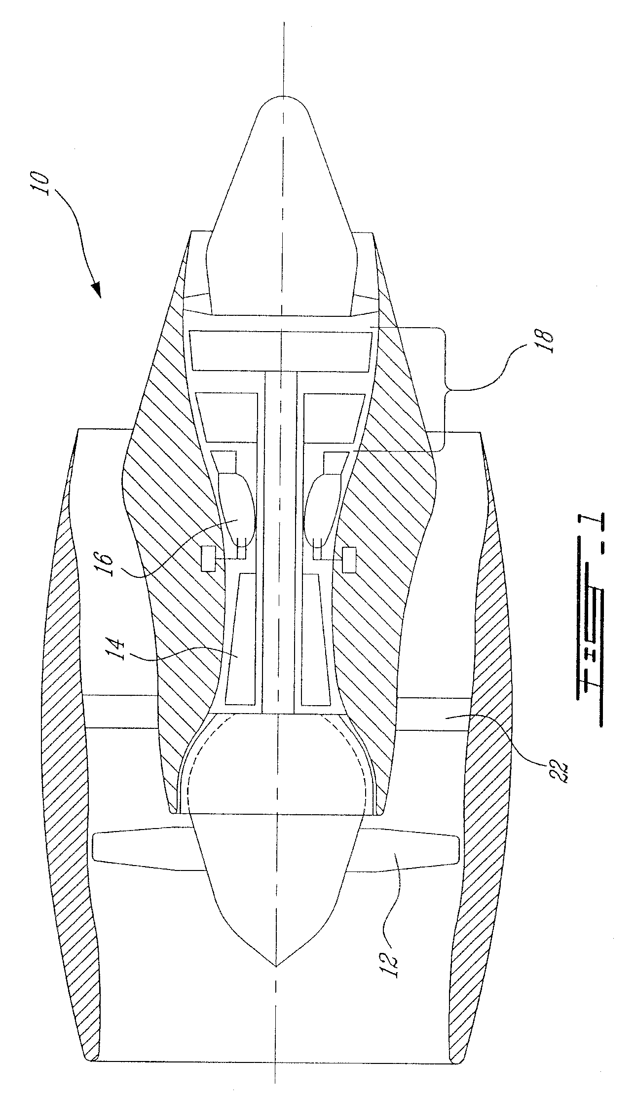
[0020]FIG. 1 illustrates a gas turbine engine 10 of a type preferably provided for use in subsonic flight, generally comprising in serial flow communication a fan 12 through which ambient air is propelled, a multistage compressor 14 for pressurizing the air, a combustor 16 in which the compressed air is mixed with fuel and ignited for generating an annular stream of hot combustion gases, and a turbine 18 for extracting energy from the combustion gases.

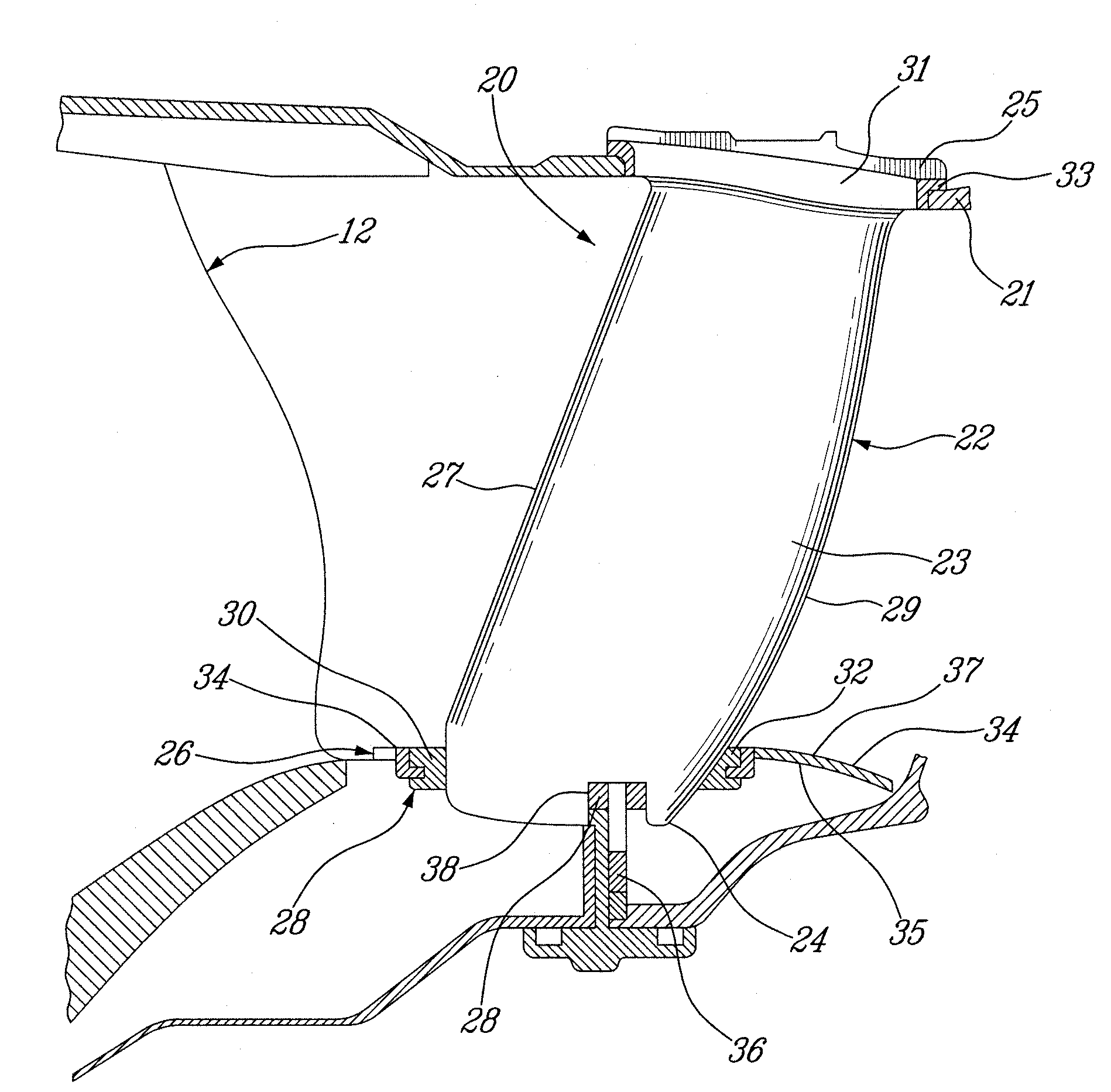
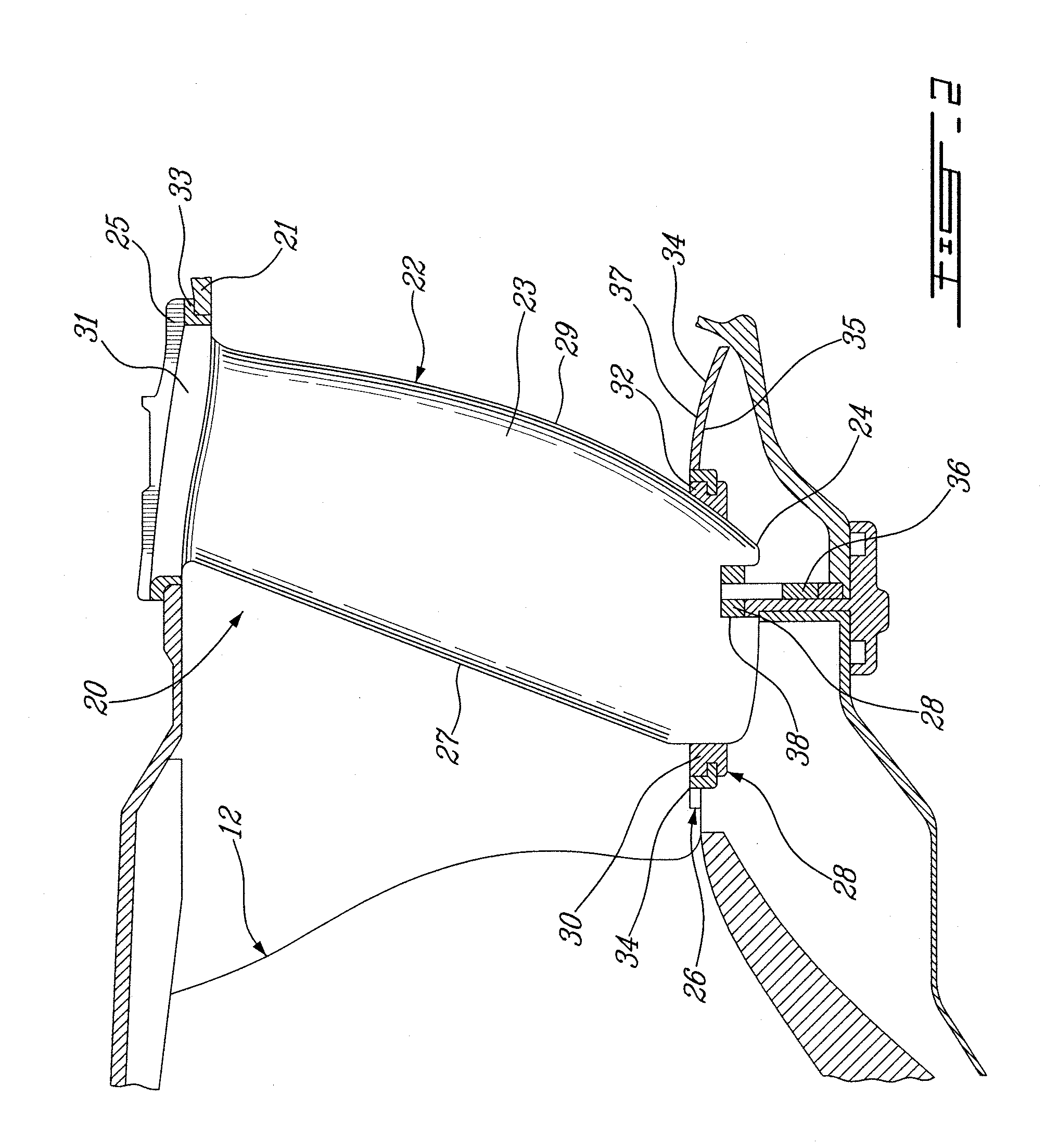
[0021]Referring to the FIG. 2, the vane assembly 20 is located downstream of the fan 12. The vane assembly 20 includes an inner shroud 26 and a plurality of vanes 22 extending radially between the inner shroud 26 and an engine casing or an outer shroud 21. The inner shroud 26 includes a shroud ring 34 and a shroud web 36. Each of the vanes 22 has an airfoil portion 23 extending between the vane tip 24 and the vane root 25. The vane root 25 is attached to the outer shroud 21 and the vane tip 24 is retained in a grommet 28 inserted into ...


PUM


Abstract

A vane including a root, a tip and an airfoil portion extending between the root and the tip, the vane also including a button portion interconnecting the airfoil portion and the root. The button portion protrudes beyond a profile of the airfoil a distance less than the root. The button portion includes leading and trailing ends free of sharp edges. The leading and trailing ends respectively protrude beyond leading and trailing edges of the airfoil portion.

Description

CROSS-REFERENCE TO RELATED APPLICATIONS[0001]This is a continuation of U.S. patent application Ser. No. 11 / 223,129, filed on Sep. 12, 2005, the specification of which is incorporated herein by reference.TECHNICAL FIELD[0002]The invention relates generally to gas turbine engines, and particularly to improved vanes provided therein downstream of the engine fan or low pressure compressor.BACKGROUND OF THE ART[0003]Gas turbine engine vane assemblies are usually provided downstream of the engine fan and / or of a low pressure compressor to reduce the swirl in the air flow exiting the compressor. Such vane assemblies must be resistant to foreign object damage while having a minimum weight.[0004]It is known to provide an inner shroud with slots receiving the vane tips in order to retain them. In such a configuration, a grommet is inserted in the slot such as to surround the vane tip thereby isolating the vane tip from the shroud. However, during a foreign object damage event a vane which is ...

Claims


Application Information

Patent Timeline
Patent Type & Authority Patents(United States)
IPC IPC(8): F03B11/02
CPCF01D9/042F02C7/05F05D2260/30
Inventor BARNETT, BARRYDENIS, DAVID
Owner PRATT & WHITNEY CANADA CORP
Learn More