Impact power tool

a power tool and impact technology, applied in the field of power tools, can solve the problems of power loss, the effect of gear engagement on the other side, and the likelihood of interference between the two

Inactive Publication Date: 2009-02-24
CHUNG LEE HSIN CHIH
View PDF14 Cites 53 Cited by
  • Summary
  • Abstract
  • Description
  • Claims
  • Application Information

AI Technical Summary

Benefits of technology

[0009]A primary objective of the present invention is to provide an impact power tool to solve the drawback of the conventional design that the gears interfere with each other at the moment of switching the output speeds.
[0010]Another objective of the present invention is to provide an impact power tool to solve the drawback of the conventional design that too many drive members cause power loss.

Problems solved by technology

Thus the gear engagement is likely to interfere with each other when the speed of the rotational output is switched.
Moreover, the conventional impact power tool has too many drive members, and therefore it causes power loss.

Method used


Image

  • Impact power tool
  • Impact power tool
  • Impact power tool

Examples


Embodiment Construction

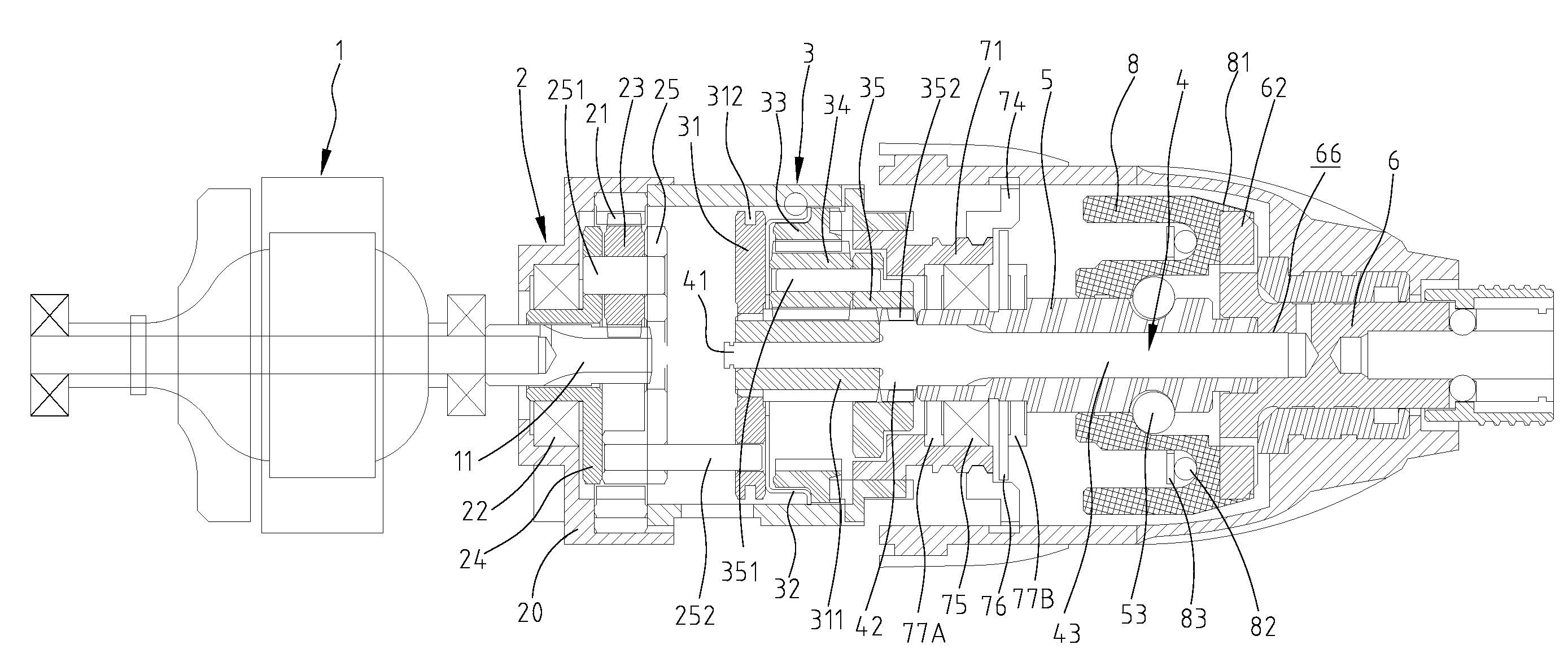
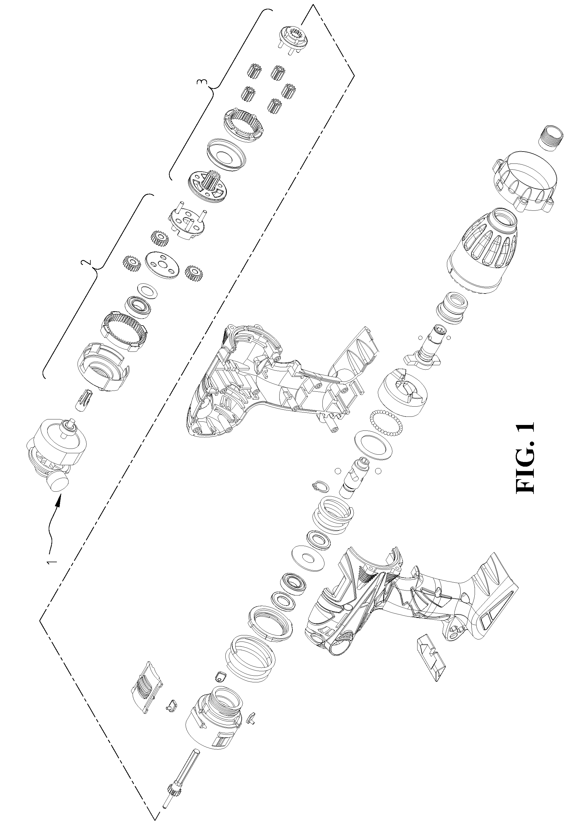
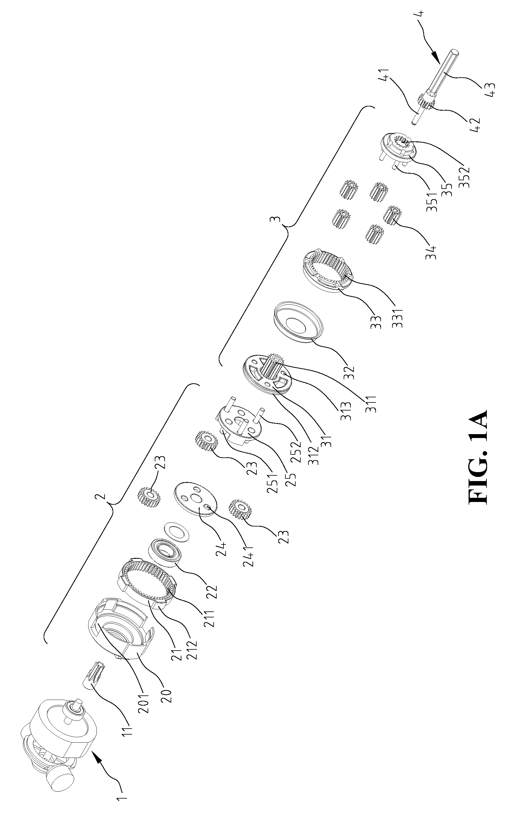
[0021]Referring to FIGS. 1, 1A, 1B and 2, an impact power tool constructed in accordance with the present invention comprises a motor 1, a first planetary gear set 2, a second planetary gear set 3, a transmission shaft 4, an intermediate shaft 5, an output shaft 6, a torque-adjusting device 7 and an hammer seat 8.

[0022]Referring to FIGS. 1A and 2, the motor 1 is provided with a drive gear shaft 11. The first planetary gear set 2 comprises a shell 20 having a plurality of notches 201 at the sidewall thereof. A first ring gear 21 is assembled within the shell 20. An inner cylindrical surface of the first ring gear 21 is provided with a plurality of internal teeth 211, and an outer cylindrical surface of the first ring gear 21 is provided with a plurality of projections 212 corresponding to the notches 201. When the first ring gear 21 is assembled within the shell 20, the projections 212 engage with the notches 201 to prevent the relative rotation between the first ring gear 21 and the...


PUM


Abstract

An impact power tool includes a motor, a first planetary gear set, a clutch having a sun gear, a second planetary gear set, a transmission shaft, an intermediate shaft, an impact seat and an output shaft. When the clutch moves to a first position, the transmission shaft engages with a second planet carrier of the second planetary gear set and the output shaft. The power of the motor is transmitted to the output shaft via the first planetary gear set, the second planetary gear set, and the transmission shaft in low-speed mode. When the clutch moves to a second position, the transmission shaft disengages from the second planet carrier and the output shaft. The power of the motor is output to the output shaft via the first planetary gear set, the second planetary gear set, the transmission shaft, the intermediate shaft, and the impact seat in high-speed-with-impact mode.

Description

BACKGROUND OF THE INVENTION[0001]1. Field of the Invention[0002]The present invention relates generally to a power tool and in particular to an impact power tool having various speeds.[0003]2. The Prior Arts[0004]A conventional power tool used for drilling, screw driving, etc transmits power from a motor to an output shaft via gear systems at various speeds. Moreover, some power tools provide impact function to easily tighten or loosen screws.[0005]Referring to FIG. 4, a conventional impact power tool comprises a motor 1, a first planetary gear set 2, a second planetary gear set 3, a clutch 31, a connecting bar R, an intermediate shaft 5, an output shaft 6 and a hammer seat 8. A drive gear shaft 11 mounted on the motor 1 engages with first planet gears 23 of the first planetary gear set 2. The first planet gears 23 are pivotally connected to a first planet carrier 25 with planet gear shafts 251. A plurality of clutch shafts 252 connects the first planet carrier 25 with the clutch 31...

Claims


Application Information

Patent Timeline
Patent Type & Authority Patents(United States)
IPC IPC(8): F16H48/06
CPCB25B21/02F16H3/64F16H2200/0034F16H2200/2007
Inventor CHEN, TING KUANG
Owner CHUNG LEE HSIN CHIH
Why Eureka
Try Eureka