
Overmolded grasper jaw

a grasper and jaw technology, applied in the field of surgical graspers, can solve the problems of high cost and time consumption of all these processes, and achieve the effects of facilitating the opening facilitating the closing of the jaw spine, and increasing the mechanical advantage of opening the jaw spin

Active Publication Date: 2009-02-24
APPL MEDICAL RESOURCES CORP
View PDF87 Cites 1376 Cited by
  • Summary
  • Abstract
  • Description
  • Claims
  • Application Information

AI Technical Summary

Benefits of technology

The present invention is a surgical instrument that includes a camming mechanism for opening and closing jaw spines. The instrument has a tube with an actuation rod and two jaw spines that pivotally connect to the tube. The jaw spines have camming surfaces and interior camming surfaces that work together to close the jaws when the camming rod moves proximally. The camming rod rides along the interior camming surface of the jaw spines to open and close the jaws. The instrument also has windows that allow the gear teeth to rotate and the jaw spines to pivot in opposite directions to an open position. The technical effects of the invention include a simplified and cost-effective manufacturing process, improved mechanical advantage for opening and closing the jaws, and the ability to apply atraumatic pads.

Problems solved by technology

All of these processes are relatively expensive and time consuming since the jaws must end up with outer surfaces and edges which are atraumatic to body tissue.

Method used


Image

  • Overmolded grasper jaw
  • Overmolded grasper jaw
  • Overmolded grasper jaw

Examples


Embodiment Construction

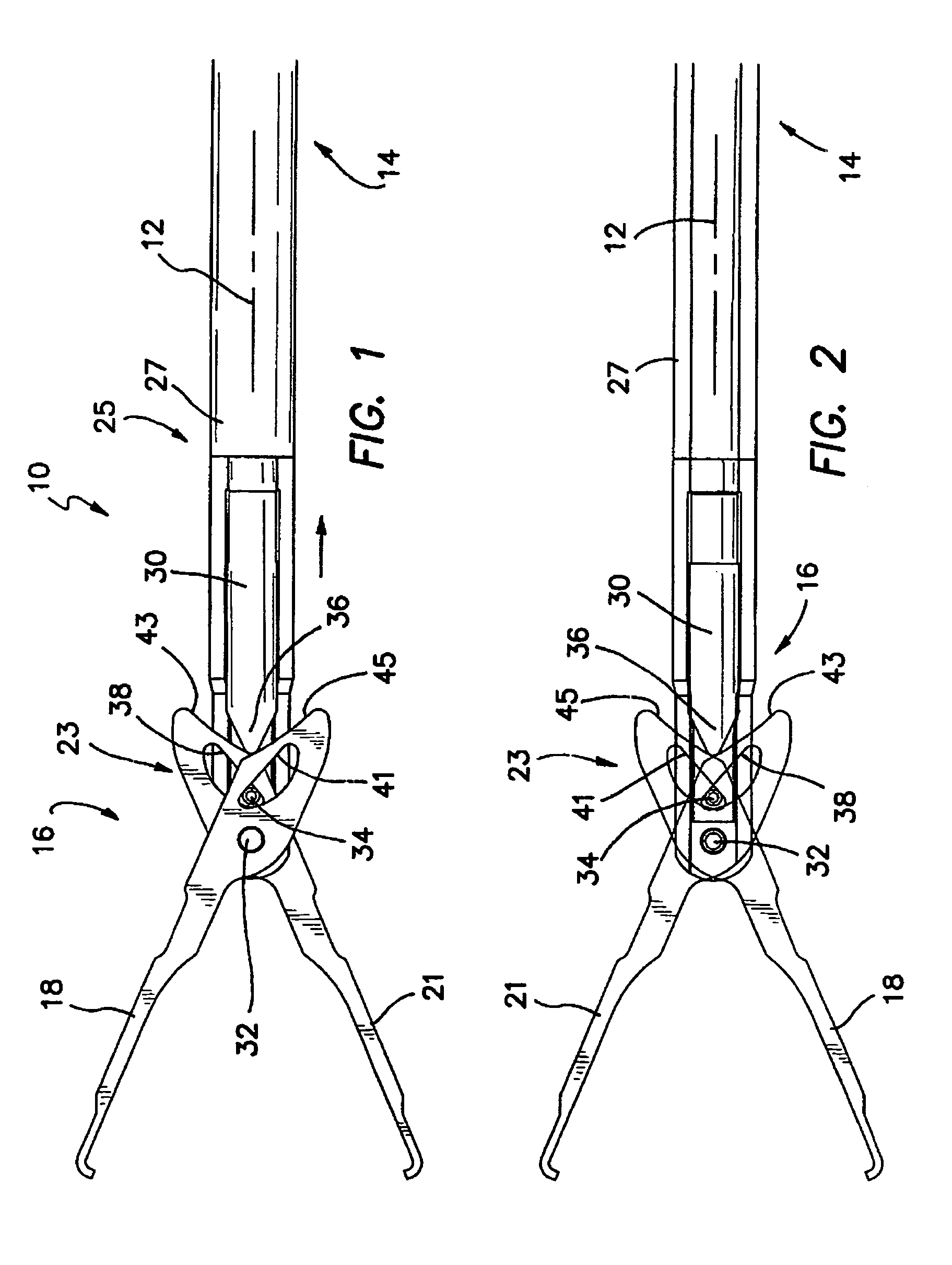
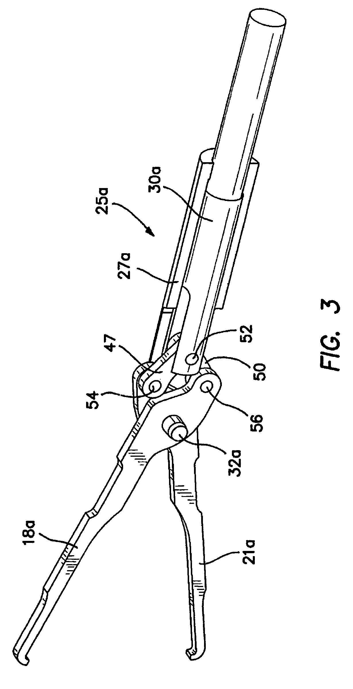
[0032]A surgical grasper is illustrated in FIG. 1 and designated by the reference numeral 10. The grasper is an elongate device having an axis 12 which extends between a proximal end 14 and a distal end 16. A pair of opposing jaw spines 18 and 21, disposed at the distal end 16, are operable between opened and closed positions by an actuation mechanism 23. A shaft assembly 25 extends along the axis 12 and includes an outer tube 27 and an inner actuation rod 30. The spines 18 and 21 are pivotally attached to the outer tube 27 by a common pivot pin 32.

[0033]The actuation mechanism 23 includes a distal camming pin 34 and a proximal camming projection 36. Both the pin 34 and projection 36 are carried by the actuation rod 30 which is moveable axially within the outer tube 27.

[0034]The camming pin 34 rides on two interior camming surfaces 38 and 41 each of which defines a slot in one of the jaw spines 21 and 18, respectively. When the actuation rod 30 is moved proximally, the camming pin 3...


PUM


Abstract

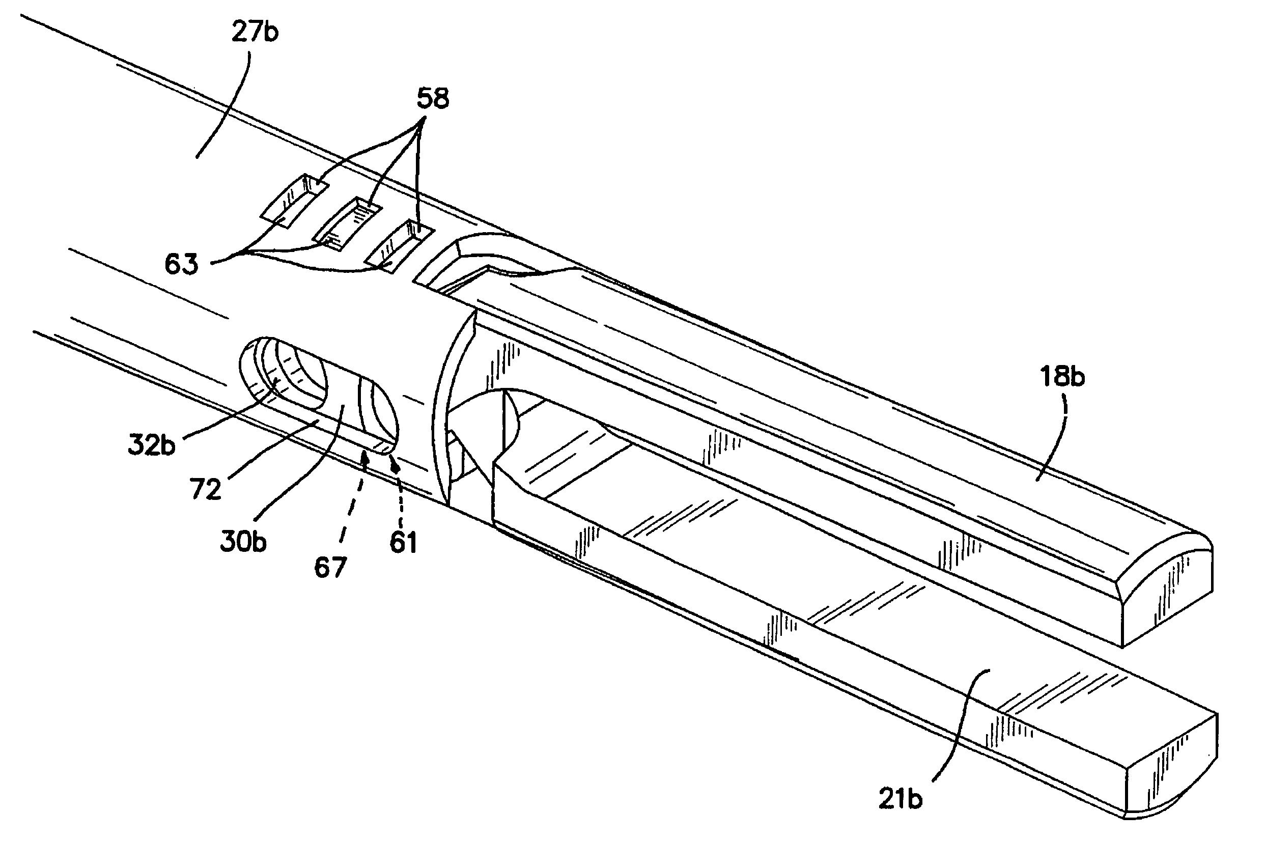
The invention is directed to a surgical instrument comprising an elongate tube extending along an axis including a camming rod and an actuation mechanism operably connected to the camming rod, the camming rod having a camming pin and a camming projection; a first jaw spine having a first cam slot, a first interior camming surface, and a first exterior camming surface; and a second jaw spine having a second cam slot, a second interior camming surface, and a second exterior camming surface, the second jaw spine pivotally connected to the first jaw spine at a common pivot pin operably connected to the elongate tube to open and close the jaw spines in response to movement of the actuation mechanism. The camming pin rides along the first and second interior camming surfaces and operates to close the jaw spines when the camming rod is moved proximally. When the camming rod moves distally, the camming projection rides on the first and second exterior camming surfaces formed on the proximal sides of the respective first and second jaw spines and operates to open the jaw spines. A feature of the invention is one camming surface on each jaw spine can facilitate closing the jaw spines while the other camming surface on each jaw spine can facilitate opening the jaw spines. These two camming surfaces on each jaw spine can be widely separated. The jaw spines can be formed of a metallic material and are overmolded with an atraumatic plastic material. By overmolding the plastic onto the metal spine, an atraumatic outer surface can be formed of the plastic material along with a high degree of detail.

Description

[0001]This is a non-provisional application claiming the priority of provisional application Ser. No. 60 / 519,849, filed on Nov. 12, 2003, entitled “Overmolded Grasper Jaw and Double Camming Actuation Mechanism,” which is fully incorporated herein by reference.BACKGROUND OF THE INVENTION[0002]1. Field of the Invention[0003]This invention generally relates to surgical graspers having opposing jaws and, in particular, to composite grasper jaws and mechanisms for actuating the jaws.[0004]2. Discussion of Related Art[0005]In the past, grasper jaws have been formed of metal in order to provide strength and reliability. Various processes of forming the metal have included stamping, EDM (Electrical Discharge Machining), photochemical etching, water jet cutting, laser cutting, and machining. All of these processes are relatively expensive and time consuming since the jaws must end up with outer surfaces and edges which are atraumatic to body tissue. In addition, the actuation mechanisms of t...

Claims


Application Information

Patent Timeline
Patent Type & Authority Patents(United States)
IPC IPC(8): A61B17/28
CPCA61B17/282A61B17/29A61B2017/2825A61B2017/2902A61B2017/2933A61B2017/2934A61B2017/2936A61B2017/2943
Inventor AHLBERG, RUSSELL E.TAYLOR, SCOTT V.OKIHISA, DAVIDBOYCHUCK, GREGORY I.KARAPETIAN, EMILSTOUT, JOHN
Owner APPL MEDICAL RESOURCES CORP
Learn More