Triplexer circuit

a technology of triplexer and circuit, applied in the field of triplexer circuit, can solve the problems of circuit complexity, inability to obtain sufficient characteristics, and inability to obtain impedance matching, and achieve the effect of excellent signal separation

Active Publication Date: 2009-02-24
TDK CORPARATION
View PDF3 Cites 10 Cited by
  • Summary
  • Abstract
  • Description
  • Claims
  • Application Information

AI Technical Summary

Benefits of technology

[0010]In view of the drawback, it is desirable to provide a triplexer circuit obtaining an impedance matching in each of frequency bands with a simple configuration and achieving excellent signal separation.
[0012]In the triplexer circuit according to an embodiment of the invention, for signals in the pass frequency band of one filter module, the other two filter modules form a parallel resonant circuit. In this case, the total impedance of the whole parallel resonant circuit becomes ∞ and, for the pass frequency band of one filter module, the other two filter modules as a whole become open. Therefore, in the pass frequency band of one filter module, the other two filter modules do not exert an influence on the filter characteristic of the one filter module, so that excellent signal separation is performed.
[0019]In the configuration, phase adjustment can be performed in the phase shifter. Consequently, for example, as compared with the case where each filter module is constructed only by a filter, an impedance matching can be easily adjusted.
[0039]In the triplexer circuit according to an embodiment of the invention, three filter modules are connected in parallel with each other and, for signals in a pass frequency band of one of the filters, the other two filters form a parallel resonant circuit. Therefore, the total impedance of the whole parallel resonant circuit becomes infinite (∞) and the other two filters can be made open to the pass frequency band of the one filter. With the simple configuration in which the three filters are connected in parallel with each other, an impedance matching is obtained in each of the frequency bands, and excellent signal separation can be performed.

Problems solved by technology

In the case of constructing a duplexer, only by simply and singly connecting filters 101 and 102 in parallel, an impedance matching cannot be obtained and a problem occurs such that sufficient characteristics cannot be obtained.
On the other hand, in the case of using the configuration described in JP-A No. 2003-198309 for a triplexer, total four filter circuit parts are provided to separate signals in three frequency bands, so that there is a problem such that the circuit is complicated.
However, in the case of a triplexer, the number of filters to be open is two, so that the conditions of the electric length cannot be simply determined unlike a duplexer.

Method used


Image

  • Triplexer circuit
  • Triplexer circuit
  • Triplexer circuit

Examples


first embodiment

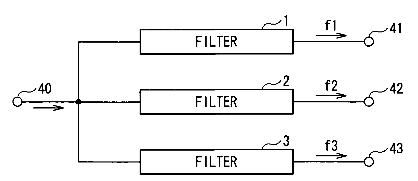
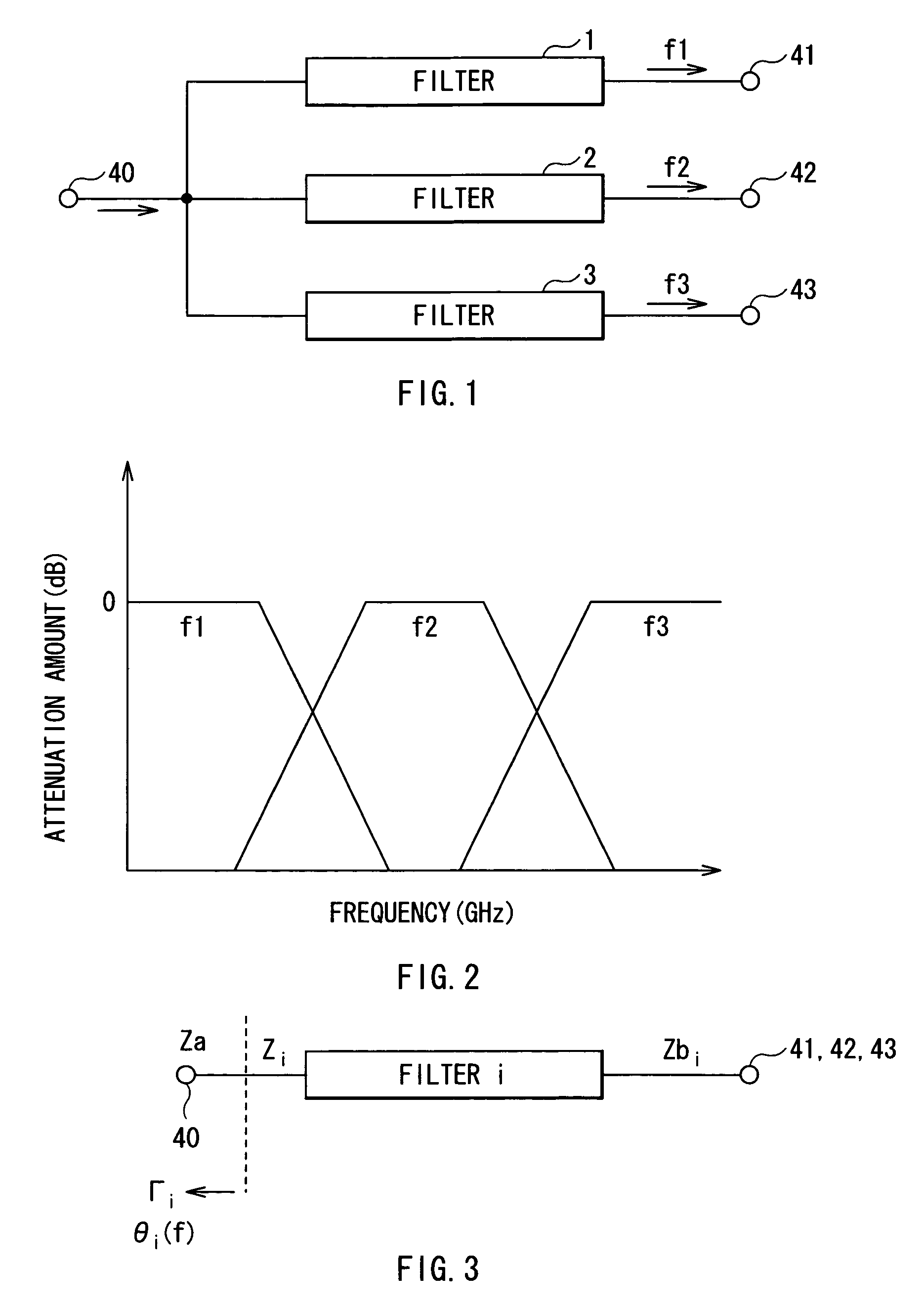
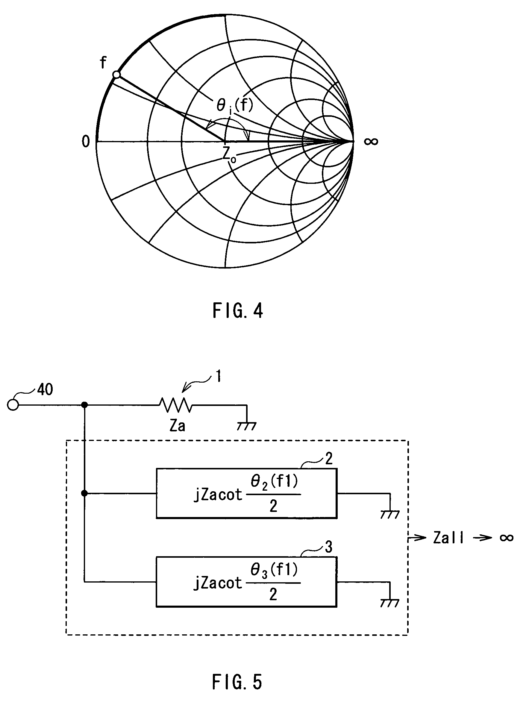
[0064]First, a triplexer circuit according to a first embodiment of the invention will be described. FIG. 1 shows an example of the configuration of a triplexer circuit according to the first embodiment. The triplexer circuit separates an input signal into signals in three frequency bands which are different from each other and is configured by connecting three filter modules in parallel with each other. Each of the filter modules is constructed by a single filter. That is, the triplexer circuit has a first filter 1 as the first filter module, a second filter 2 as the second filter module, and a third filter 3 as the third filter module. The input sides of the first, second, and third filters 1, 2, and 3 are connected to a common input port 40. The output side of the first filter 1 is connected to a first output port 41, the output side of the second filter 2 is connected to a second output port 42, and the output side of the third filter 3 is connected to a third output port 43. Th...

second embodiment

[0100]A triplexer circuit according to a second embodiment of the invention will be described.

[0101]FIG. 8 shows an example of the configuration of a triplexer circuit according to the second embodiment. The same reference numerals are designated to substantially the same components as those of the triplexer circuit according to the first embodiment and their description will not be repeated. In the foregoing first embodiment (FIG. 1), the case where each of the filter modules is constructed by a single filter, and the first, second, and third filters satisfy the predetermined conditions (A1), (A2), and (A3), respectively, has been described. However, there may be a case where filters are designed and, as a result, the filters do not satisfy the conditions. In the second embodiment, a phase shifter for characteristic adjustment is provided so as to deal with such a situation.

[0102]In the triplexer circuit according to the second embodiment, each of filter modules is configured to ha...

third embodiment

[0112]Next, a triplexer circuit according to a third embodiment of the invention will be described.

[0113]FIG. 9 shows an example of the configuration of a triplexer circuit according to the third embodiment. The same reference numerals are designated to substantially the same components as those of the triplexer circuit according to the first and second embodiments and their description will not be repeated. In the foregoing second embodiment (FIG. 8), the case where a phase shifter for characteristic adjustment is provided in a front stage of each of the filters has been described. The triplexer circuit according to the third embodiment has a transmission line as the phase shifter and performs characteristic adjustment by the transmission line.

[0114]In the triplexer circuit according to the third embodiment, each of filter modules is constructed by a filter and a transmission line provided at the front stage of the filter and in series with the filter. Specifically, the triplexer c...


PUM


Abstract

The present invention provides a triplexer circuit obtaining an impedance matching in each of frequency bands with a simple configuration and separating a signal excellently. Three filters are connected in parallel with each other and, for signals in a pass frequency band of one of the filters, the other two filters form a parallel resonant circuit. In this case, the total impedance of the whole parallel resonant circuit becomes infinite (∞) and the other two filters can be made open to the pass frequency band of the one filter. With the simple configuration in which the three filters are connected in parallel with each other, an impedance matching is obtained in each of the frequency bands, and excellent signal separation can be performed.

Description

CROSS REFERENCE TO RELATED APPLICATIONS[0001]The present invention contains subject matter related to Japanese Patent Application JP 2005-156278 filed in the Japanese Patent Office on May 27, 2005, the entire contents of which being incorporated herein by reference.BACKGROUND OF THE INVENTION[0002]1. Field of the Invention[0003]The present invention relates to a triplexer circuit for separating an input signal into signals of three frequency bands which are different from each other.[0004]2. Description of the Related Art[0005]Hitherto, there is a duplexer that receives signals of two different frequency bands by a single antenna and separates the signals into the different bands. Such a duplexer is realized by connecting first and second filters 101 and 102 for passing only signals in their bands in parallel with each other as shown in FIG. 20.[0006]In recent years, a triplexer for separating signals of three frequency bands which are different from each other into their bands has ...

Claims


Application Information

Patent Timeline
Patent Type & Authority Patents(United States)
IPC IPC(8): H01P5/12H03H7/46
CPCH04B1/52H04L25/0278H03H2250/00H04B1/0053
Inventor FUKUNAGA, TATSUYA
Owner TDK CORPARATION
Why Eureka
Try Eureka