Panel display and display

a technology for panel displays and display units, applied in the field of panel displays, can solve the problems of heavy weight of the members necessary for holding the display unit on the wall, difficult to securely hold the display unit in a space, dangerous to hold the display unit in such a state, etc., and achieves the effect of high safety, low cost and high safety

Inactive Publication Date: 2009-02-24
FUNAI ELECTRIC CO LTD
View PDF5 Cites 13 Cited by
  • Summary
  • Abstract
  • Description
  • Claims
  • Application Information

AI Technical Summary

Benefits of technology

[0014]The present invention discloses to provide a panel display and a display capable of being highly safely mounted on a wall without spoiling appearance, of being manufactured at a low cost, and of eliminating disadvantages resulting from the providing the display with the mounting structure necessary only for mounting the display on a wall.
[0028]Therefore, a greater number of the through holes may be formed in a rear part of the base on the rear side of the display unit supported on the post with the fixing part thereof fastened to the post. Thus the number of the screws visible to the user can be reduced when the display is set in the normal position for use and the aesthetic appearance of the display will not be spoiled.
[0035]The post has a flat part provided with post's through holes, and rails rising substantially perpendicularly to the flat part from the opposite side edges of the flat part. The depressed part may be provided with grooves, in which the rails engage, formed in a back wall provided on its back surface with internally threaded parts to guide the post into the depth of the depressed part. The post is fastened to the depressed part by fitting the post deep into the depressed part with the rail parts engaged in the grooves and fastening the post to the back wall with screws passed through the post's through holes formed in the post and screwed in the internally threaded parts of the back wall. Thus the post can be fastened to the back wall with screws passed through the through holes of the post and those of the back wall with the post fitted deep in the depressed part and the rail parts engaged in the grooves. Therefore, the display unit thus securely supported in the air facilitates fastening work.
[0037]The base has an outline within a region surrounded by the outline of the display unit when the post is fastened to the depressed part. When the base is thus formed, the base of the stand is concealed entirely by the display unit when the display unit is mounted on a wall. Therefore, stand is not visible to the user on the front side of the display unit and hence the display mounted on a wall has an aesthetically satisfactory appearance.

Problems solved by technology

Those members necessary for holding the display unit on the wall are heavy.
Consequently, it is difficult to securely hold the display unit in a space apart from the wall and it is dangerous to hold the display unit in such a state.
As obvious from FIG. 7 of JP-A-2001-236024, the stand is visible from the front side of the display unit mounted on the wall, which is aesthetically undesirable.
The monitor mentioned in JP-A-2006-154842 needs an additional member, namely, the base bracket to be mounted on the wall, which requires an additional monetary cost.
Therefore, the stand is visible when the liquid crystal display unit mounted on the wall is used, which is aesthetically undesirable.
Thus such a display is expensive.
Bosses need to be formed beforehand on the display and screws are necessary to hold the mounting structure fixedly in the case of the display, leading to high production costs.
Consequently, it is difficult to determine the layout of electronic devices in the case and to determine the sizes of the electronic devices, which enhances the degree of difficulty in manufacturing the display and increases the manufacturing cost of the display.
Under the recent circumstances requiring reducing the thickness of the display, it is scarcely possible to space the mounting structure apart from the inside surface of the back wall of the case when the mounting structure is disposed in the case.
Therefore, minute vibrations of the mounting structure will cause the case to vibrate and generate noise.

Method used


Image

  • Panel display and display
  • Panel display and display
  • Panel display and display

Examples


Embodiment Construction

[0048]The detailed description set forth below in connection with the appended drawings is intended as description of presently preferred embodiments of the invention and is not intended to represent the only forms in which the present invention may be constructed and or utilized.

[0049]A preferred embodiment of the present invention will be described with reference to the accompanying drawings.

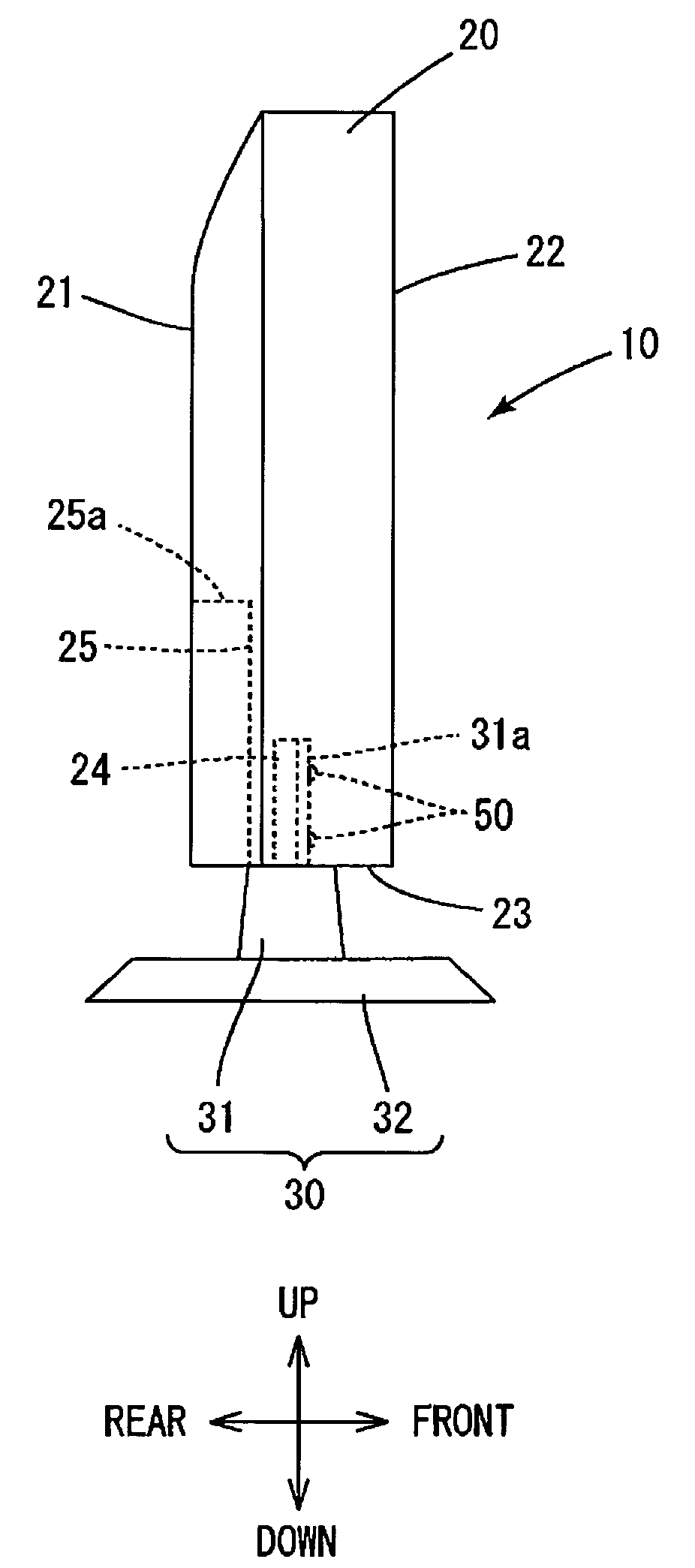
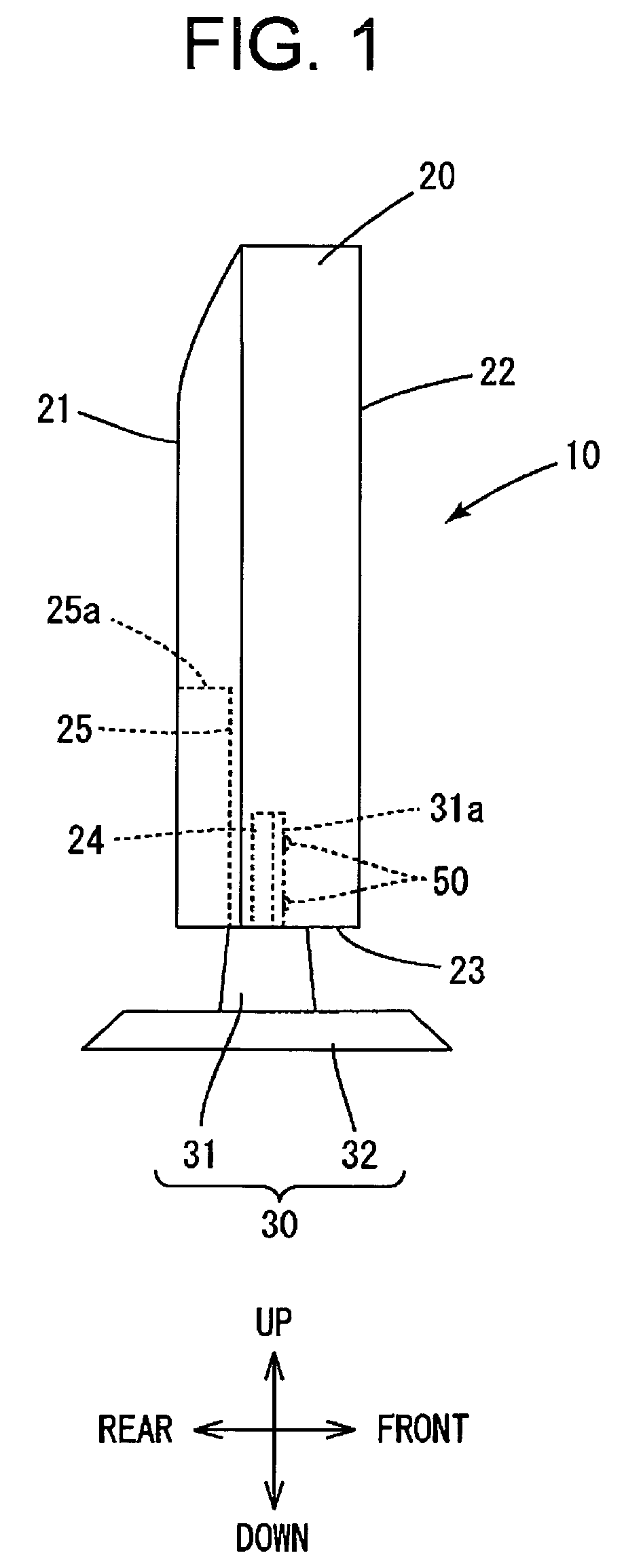
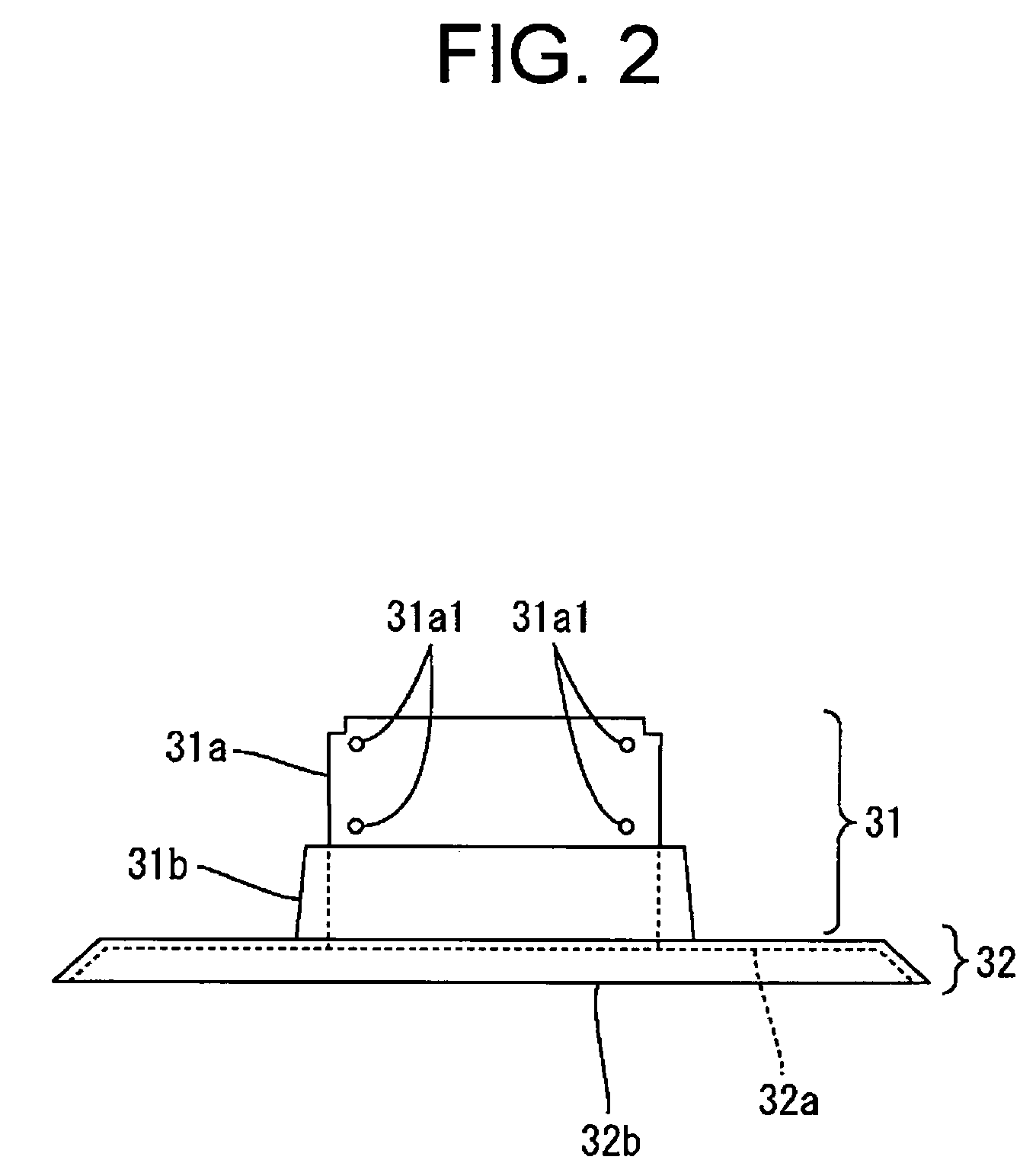
[0050]Another aspect of the present invention provides a panel display 10 capable of being mounted on a wall W, the panel display 10 comprising:[0051]a display unit 20 formed by housing a display panel 20a in a case 20b; [0052]a stand 30 supporting the display unit 20;[0053]the stand 30 having a base 32 having a substantially elliptic outline, and a post 31 extending from a substantially central part of the base 32 substantially perpendicularly to the base 32;[0054]the post 31 having a flat part 31a3 substantially parallel to the display panel 20a, and rails 31a2 formed by bending opposite sid...


PUM


Abstract

The present invention discloses a display comprising: a stand including a base and a post; a lower part of a display unit having a fixing part for fastening the post to the lower part; the stand supporting the display unit with the post fastened to the fixing part extending upward; the base of the stand is provided with a first through hole used for fastening the base to a wall; the post of the stand is provided with a second through hole used for fastening the post to the display unit; a back wall of the display unit includes a depressed part; the depressed part is provided with a threaded hole used for fastening the post to the display unit; and the stand supporting the display unit with the base fastened to the wall and the post fastened to the depressed part.

Description

CROSS-REFERENCES TO RELATED APPLICATIONS[0001]The present application is related to the Japanese Patent Application No. 2006-355789, filed on Dec. 28, 2006, the entire disclosure of which is expressly incorporated by reference herein.BACKGROUND OF THE INVENTION[0002]1. Field of the Invention[0003]The present invention relates to a panel display capable of being mounted on a wall and a display.[0004]2. Description of the Related Art[0005]A known structure disclosed in Japanese Unexamined Patent Application Publication (JP-A) No. 2001-236024 includes a tilt unit attached to the back wall of a display unit, and a stand fastened to the tilt unit with screws. The stand is separated from the tilt unit by unscrewing the screws, the stand is turned through an angle of 90°, the stand is fastened again to the tilt unit with the screws, and then the stand is fastened to a wall with its bottom surface set parallel to the surface of the wall to dispose the display unit parallel to the surface of...

Claims


Application Information

Patent Timeline
Patent Type & Authority Patents(United States)
IPC IPC(8): G06F1/16G09F9/00H04N5/64
CPCF16M11/00F16M11/22F16M13/02F16M2200/08Y10S248/918
Inventor YOKAWA, AKIRA
Owner FUNAI ELECTRIC CO LTD
Why Eureka
Try Eureka