
Three-phase voltage-fed AC/DC converter

a voltage-fed ac/dc converter and three-phase technology, applied in the direction of pulse technique, continuous tuning, single output arrangement, etc., can solve the problems of distortion of excitation voltage, difficult to reliably detect islanding operation of power network link inverter, etc., to achieve the effect of reliable detection

Inactive Publication Date: 2009-02-24
ORIGIN CO LTD
View PDF5 Cites 11 Cited by
  • Summary
  • Abstract
  • Description
  • Claims
  • Application Information

AI Technical Summary

Benefits of technology

The solution allows for autonomous parallel operation of multiple units, enhances power system reliability by independently controlling output deviations, and reliably detects islanding operations, improving the overall stability and efficiency of the power network.

Problems solved by technology

Further, the prior art power network link inverter protection method uses the fact that the excitation voltage of a distribution transformer is distorted.
Further, it is believed that the distortion of the excitation voltage depends on the relationship between the inverter capacity and the distribution transformer capacity and the like.
For this reason, in the case where the supply power and load power of the power network link inverter are roughly equal, it is difficult to reliably detect an islanding operation of the power network link inverter.

Method used


Image

  • Three-phase voltage-fed AC/DC converter
  • Three-phase voltage-fed AC/DC converter
  • Three-phase voltage-fed AC/DC converter

Examples


first embodiment

[0125]A three-phase voltage-fed AC / DC converter 12 shown in FIG. 4 is equipped with a three-phase voltage-fed AC / DC conversion circuit 40 which has internal equivalent impedance viewed from an AC terminal 22, wherein power from a DC voltage source (not shown in the drawings) is converted to three-phase AC power which is then outputted from the AC terminal 22 based on a PWM reference, an M conversion circuit 32 which converts the three-phase output voltage at the AC terminal 22 to αβ static coordinates, a U conversion circuit 33 in which the output voltage vector obtained by the M conversion circuit 32 is converted to dq rotational coordinates which are then outputted, a second superior voltage control circuit 90 which outputs a signal generated based on a superior reference vector 120 and the output voltage vector obtained by the U conversion circuit 33 as a voltage reference vector, a second inferior voltage control circuit 80 which outputs a signal generated based on a base voltag...

fourth embodiment

[0190]In comparison with the three-phase voltage-fed AC / DC converter 11 described in the fourth embodiment, the differences in the three-phase voltage-fed AC / DC converter 12 according to the present embodiment lie in the point that the signal process inside the second inferior voltage control circuit 80 is carried out in αβ static coordinates, and the point that the positive feedback circuit 200 carries out positive feedback on the superior reference vector 120 using the output from the U conversion circuit 33 obtained by conversion of the output from the M conversion circuit 32. Further, because the same structural elements as those in FIG. 14 and FIG. 18 are shown by the same symbols in FIG. 15, a description is omitted.

[0191]The M conversion circuit 32 converts one voltage of the three-phase output voltage at the AC terminal 22 as a reference to αβ static coordinates formed by an α axis and a β axis which are mutually orthogonal. The conversion matrix can be represented by Equati...


PUM


Abstract

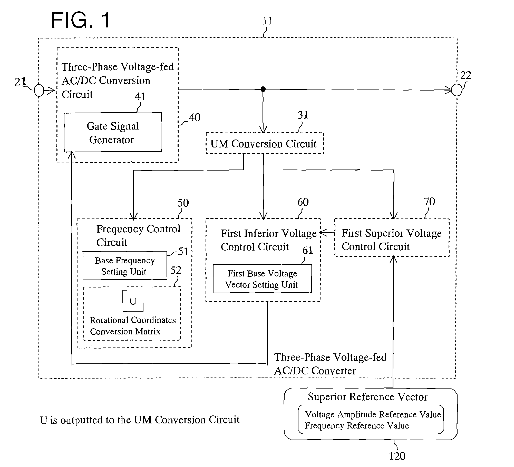
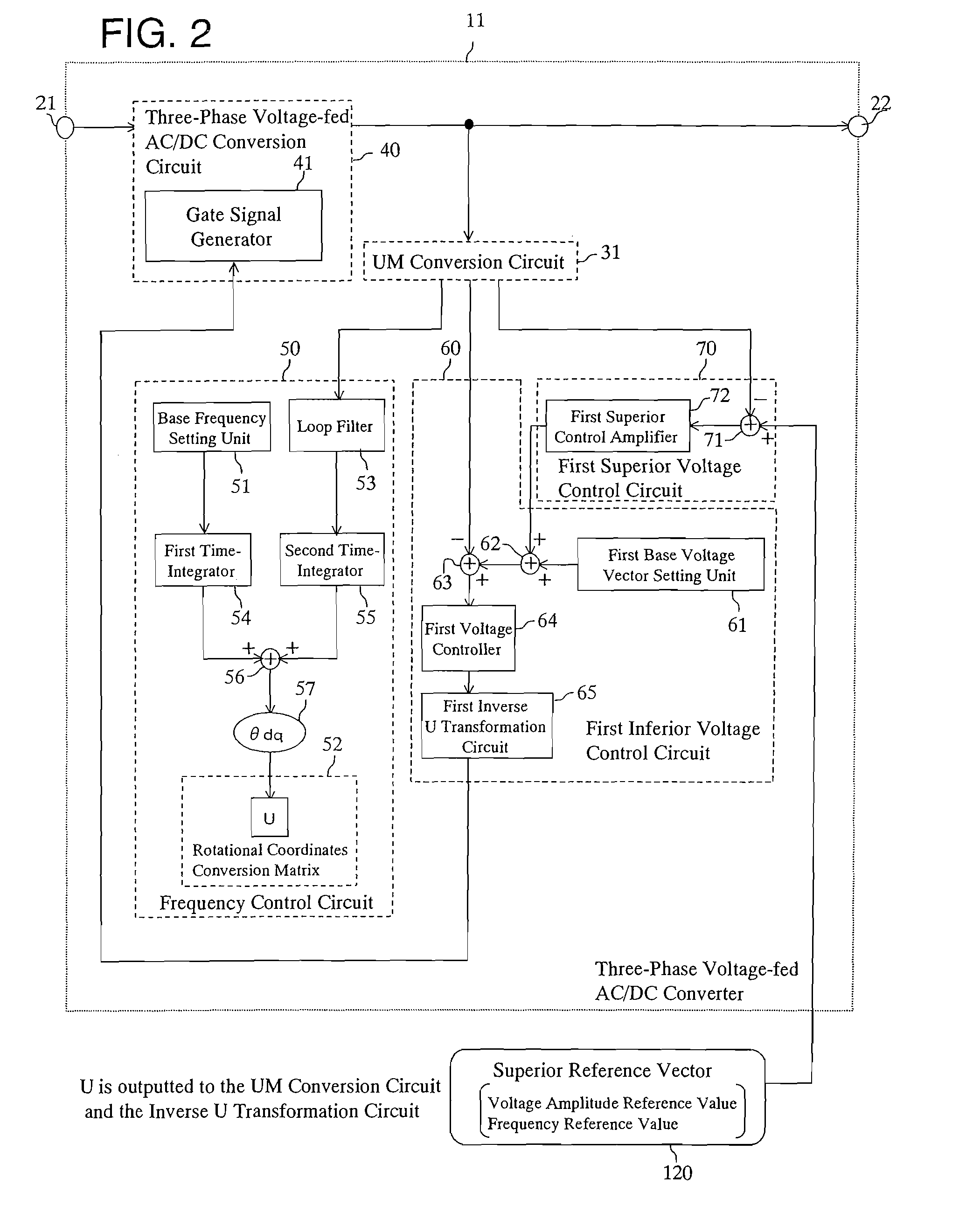
A three-phase voltage-fed AC / DC converter includes a conversion circuit which converts power from a DC voltage source to three-phase AC power. The converter further includes a UM conversion circuit which carries out dq conversion of the three-phase output voltage, a superior voltage control circuit which outputs a voltage reference vector based on a superior reference vector and an output voltage vector obtained by the UM conversion circuit, an inferior voltage control circuit which outputs a PWM reference based on the voltage reference vector and the output voltage vector, and a frequency control circuit which synchronizes a value generated based on a q-axis component from the UM conversion circuit with a rotation angle of a conversion matrix in the UM conversion circuit.

Description

[0001]The present application claims priority from Japanese Patent Application No. 2006-053487, filed Feb. 28, 2006, and Japanese Patent Application No. 2007-005918, filed on Jan. 15, 2007, the disclosures of which are hereby incorporated by reference herein in their entirety.FIELD OF THE INVENTION[0002]The present invention is related to a three-phase voltage-fed AC / DC converter which can be applied to a power network link device or an uninterruptible power supply forming a power supply of an electric power system, and a three-phase voltage-fed AC / DC converter which can be applied to an inverter that operates while connected to an electric power system.DESCRIPTION OF THE PRIOR ART[0003]Up until now, in the case where a plurality of inverters are operated while connected in parallel, the deviation between the outputs of one inverter and another inverter has been detected by a deviation detection circuit provided separately, and the output has been corrected so that the detected devi...

Claims


Application Information

Patent Timeline
Patent Type & Authority Patents(United States)
IPC IPC(8): H03J3/00H02M5/40
CPCH02M1/126H02M7/219
Inventor OHSHIMA, MASAAKISHIMIZU, HIROKAZUUSHIKI, SHUICHIFUKUI, JIROU
Owner ORIGIN CO LTD
Learn More