Fascia-mounted aluminum railing system

a technology of aluminum railings and aluminum frames, applied in the field of aluminum railing systems, can solve problems such as not being the most aesthetically pleasing constructions

Inactive Publication Date: 2009-03-03
HANSEN TRACY C +1
View PDF13 Cites 16 Cited by
  • Summary
  • Abstract
  • Description
  • Claims
  • Application Information

AI Technical Summary

Problems solved by technology

Although these designs work and provide the necessary protection, they are not the most aesthetically pleasing constructions.

Method used


Image

  • Fascia-mounted aluminum railing system
  • Fascia-mounted aluminum railing system
  • Fascia-mounted aluminum railing system

Examples


first embodiment

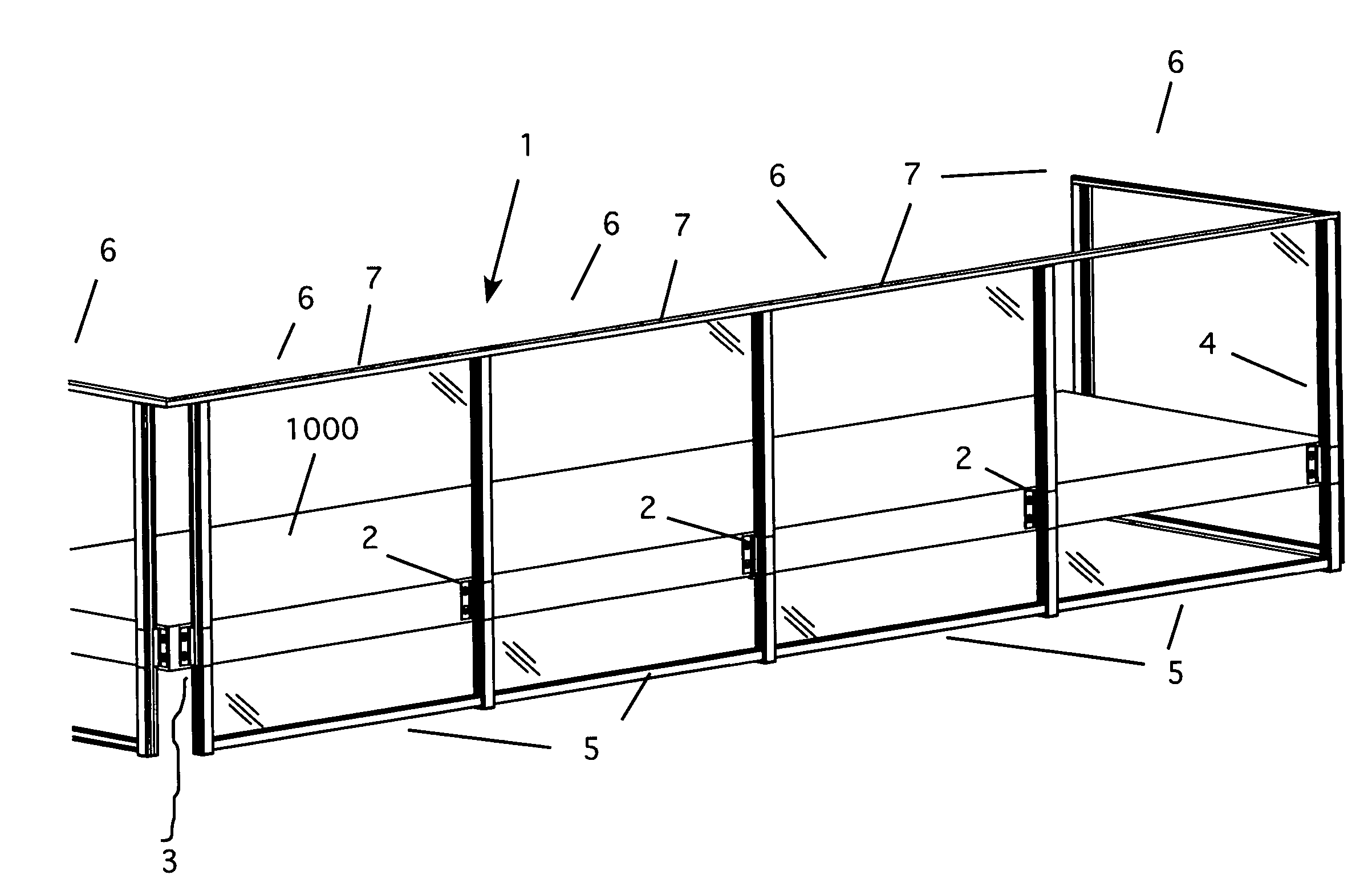
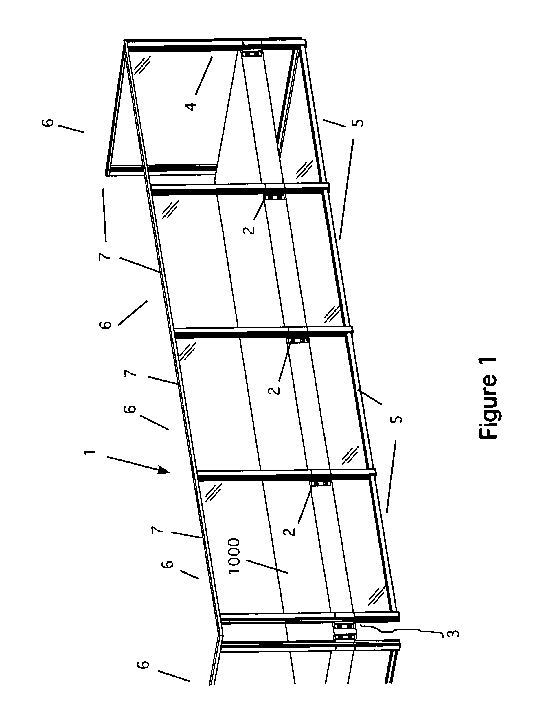
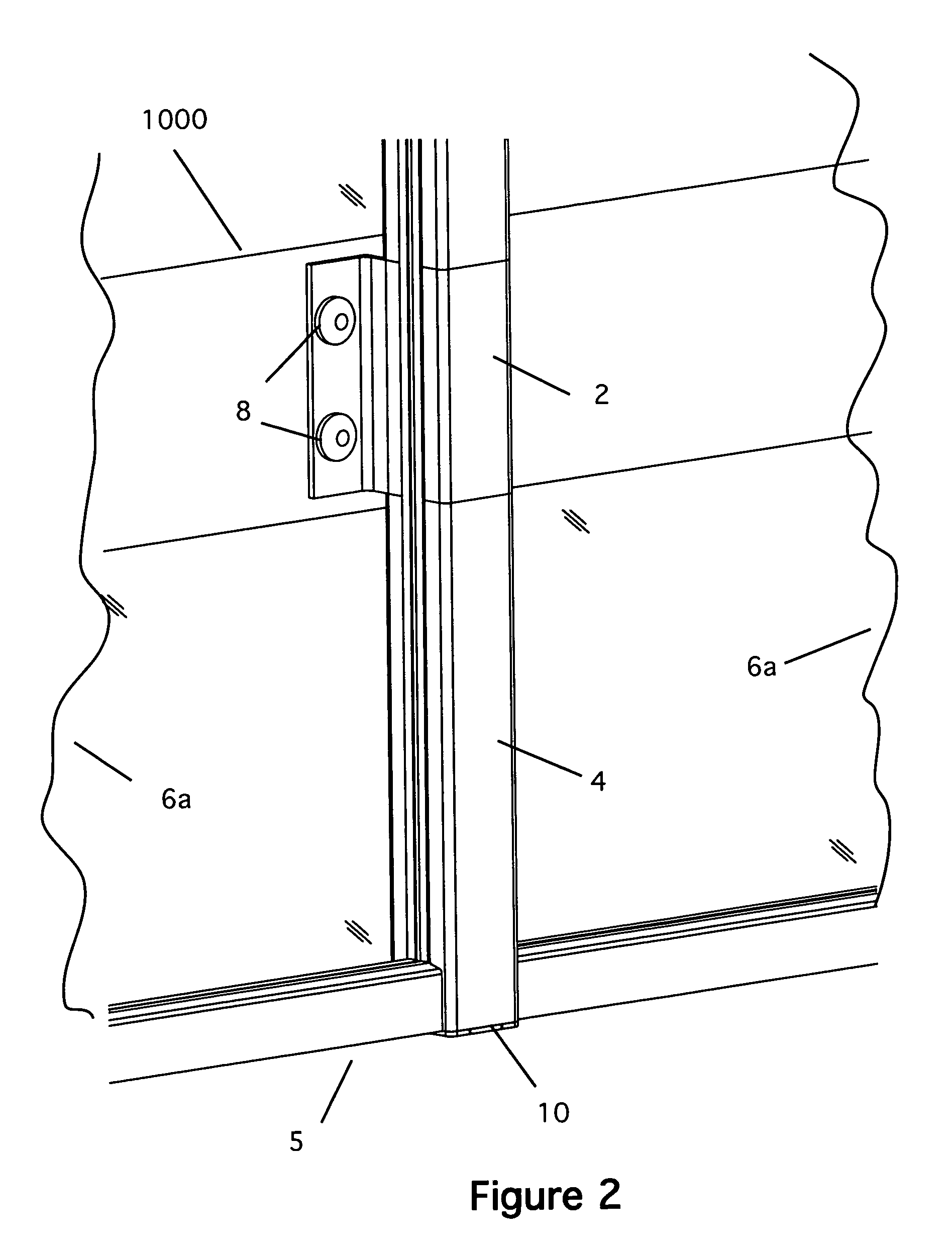
[0022]FIG. 4 is a detail view of the post-fascia bracket assembly for the Here, the fascia bracket 2 is attached to the slab 1000 as discussed above. Because of the construction of the fascia bracket (see FIG. 5), the posts cannot pass into the fascia brackets 2. Thus, to form the post and fascia assembly, the vertical post must be made of two pieces. FIG. 4 shows the upper portion 4a of the post and the lower portion 4b of the post aligned with the fascia bracket 2. Moreover, because the post portions cannot pass into the fascia brackets 2, additional supports must be provided to hold the posts in place on top of and under the fascia bracket 2. This is accomplished using two splice extrusion members 18. The splice extrusion members 18 pass through the fascia brackets as shown. They are secured using epoxy and, if necessary, appropriate fasteners. As shown in FIG. 4, the splice extrusion members 18 align with the extruded forms of the posts 4a and 4b. The post portions slide over t...

second embodiment

[0026]FIG. 8 is a cross-section of a fascia bracket extrusion for the fascia bracket. This embodiment of fascia bracket 30 has a pair of mounting flanges 20 that extends outward from the main body of the brackets, as before. The main body has two open channels 21 and a center channel 21a that one-piece post 31 (not shown). A center channel 21a joins the two channels 21 to form a pair of channels 22 for the infill panels. Note that the two open channels 21 have corner recesses 23 formed in them. These recesses receive flanges on the post members, which are similar to those formed on the splice members, as discussed above. To set the post, the post is slid into the bracket until the flanges line up with the recesses 23 in the brackets. At this point, the post is set and can be secured in place.


PUM


Abstract

An improved railing / wall system for elevated slab balconies. The system uses a number of fascia brackets to secure posts to the outer face of the elevated slab balcony. The posts have a base track secured to them. Infill panels are then placed between the posts to provide the wall structure. A top rail can be used to cover the top of the infill panels. The lower portion of the infill panels also can be tinted to conceal the face of the concrete balcony, if desired. The infill panels can be selected from a group of materials, including tempered glass, pickets, expanded metal, perforated metal, metal cut with water jets or a composite material.

Description

CROSS REFERENCE TO RELATED APPLICATIONS[0001]Not ApplicableSTATEMENT REGARDING FEDERALLY SPONSORED RESEARCH AND DEVELOPMENT[0002]Not ApplicableBACKGROUND OF THE INVENTION[0003]1. Field of the Invention[0004]This invention relates to aluminum railing systems and particularly to aluminum railing systems mounted to the face of an elevated concrete balcony slab.[0005]2. Description of the Prior Art[0006]Modern building design for high-rise apartments and other types of building structures often have concrete balconies. These balconies allow the residents to enjoy outdoor space attached to their dwelling units or offices. For safety purposes, these balconies have railing systems installed. Typically, these guardrails are fabricated from metal or concrete. Guardrails fabricated using metal are usually either surface mounted to the top of the slab using a base plate, or mounted into a core pocket. Although these designs work and provide the necessary protection, they are not the most aesth...

Claims


Application Information

Patent Timeline
Patent Type & Authority Patents(United States)
IPC IPC(8): E04H1/00E04B2/00E04C3/00
CPCE04F11/1812E04F11/1853
Inventor HANSEN, TRACY C.GREGG, LUCAS ANTHONY
Owner HANSEN TRACY C
Why Eureka
Try Eureka