
Gas monitor testing apparatus, method, and system

a gas monitor and testing apparatus technology, applied in calibration apparatus, instruments, specific gravity measurement, etc., can solve the problems of high co concentration, high risk, and widespread presence in many everyday situations, and achieve the effect of reducing testing gas and labor costs

Inactive Publication Date: 2009-03-03
AERIONICS
View PDF40 Cites 5 Cited by
  • Summary
  • Abstract
  • Description
  • Claims
  • Application Information

AI Technical Summary

Benefits of technology

"The present invention provides an improved method, apparatus, and system for testing the performance of gas monitors. It addresses the need for a faster and more cost-effective way to validate the performance of gas monitors. The invention involves a fluid coupling apparatus that can be easily attached to a gas monitor and deliver testing gas directly to the gas sensor. This reduces the time and cost of testing gas monitors, while also minimizing the need for air purging and testing gas. The invention is easy to use and reliable in operation. Overall, the invention achieves a faster and more efficient way to test gas monitors."

Problems solved by technology

CO in high concentrations is not only undetectable by humans but is also highly dangerous and widely prevalent in many everyday situations.
CO typically becomes unsafe when dangerous concentrations build-up due to, for example, poor ventilation.
CO build-up is a potential problem, for example, in energy-efficient, airtight homes, vehicles, and plants that decrease the exchange of inside and outside air.
If CO levels become so high, the monitors will issue an alarm.
Since testing procedures use testing gas, and given the relatively lengthy times required for a validating a monitor's performance, considerable testing gas may be used.
It will be appreciated that there are cost considerations when frequently using relatively expensive testing gases for the significant periods of time as noted above, especially when such costs are multiplied by the number of sensors to be monitored and the number of times the monitors will be tested.
If the testing gas is toxic, undesirable safety issues may also be present, should the gas not be handled properly or the testing procedure not be properly carried out.
This is a considerable amount of time to expend not only in terms of holding the delivery tube and plastic bag in proper position over the gas monitor, but also for using the relatively expensive testing gas.
Accordingly, not only is the amount of actual testing time at the desired level of testing gas concentration relatively lengthy, but the actual time to set-up and perform a test is increased due to additional time delays arising from setting up the test and purging the air.

Method used


Image

  • Gas monitor testing apparatus, method, and system
  • Gas monitor testing apparatus, method, and system
  • Gas monitor testing apparatus, method, and system

Examples


Embodiment Construction

[0030]The words “a”, “an”, and “the” are used interchangeably with “at least one” to mean one or more of the elements being described. By using words of orientation, such as “top”, “bottom”, “overlying”, “front”, “back” and “backing” and the like for the location of various elements in the disclosed articles, we refer to the relative position of an element with respect to a horizontally-disposed body portion. We do not intend that the disclosed articles should have any particular orientation in space during or after their manufacture.

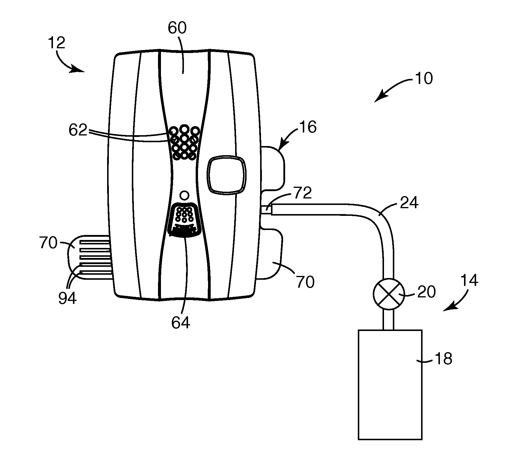
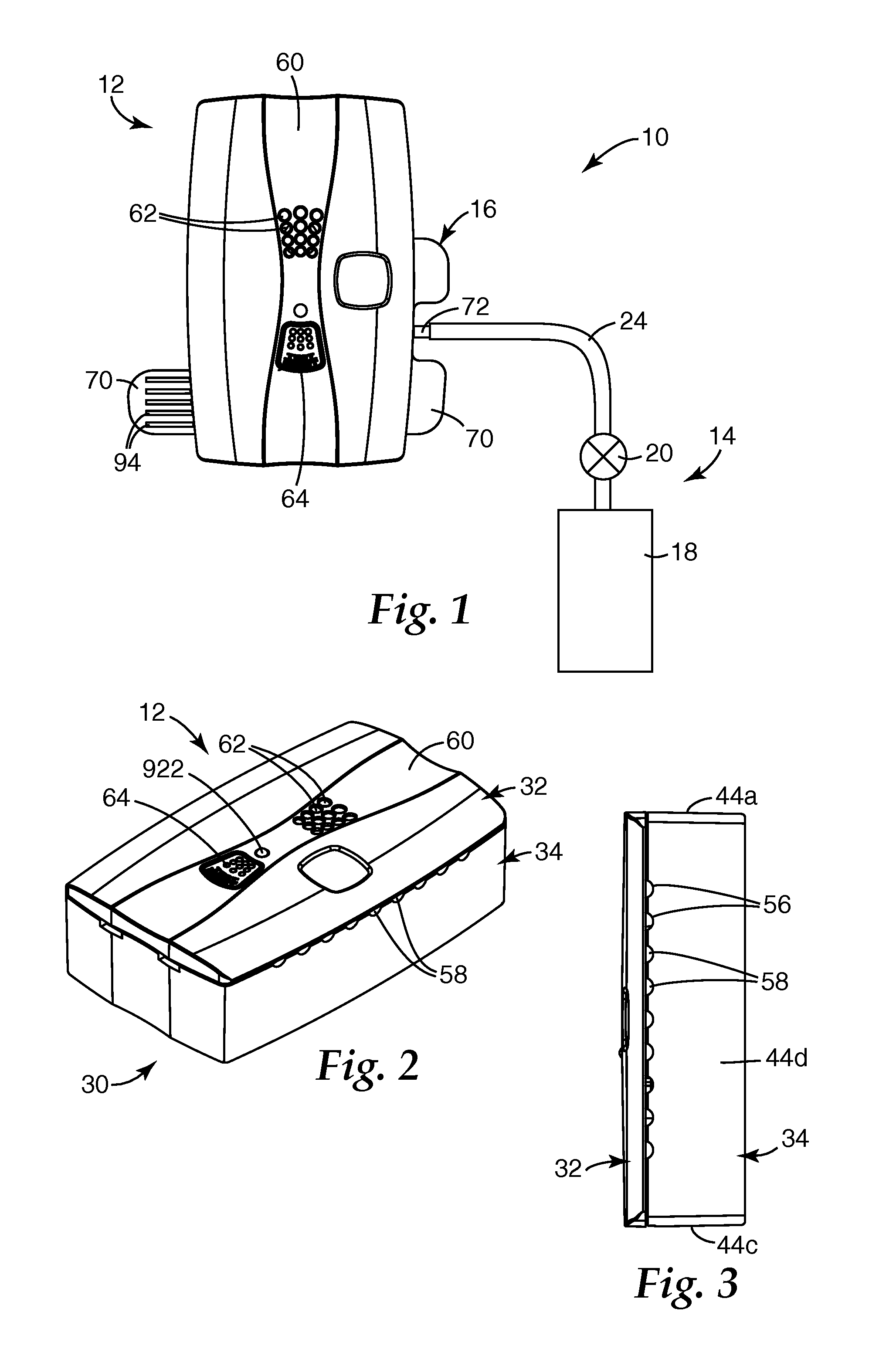
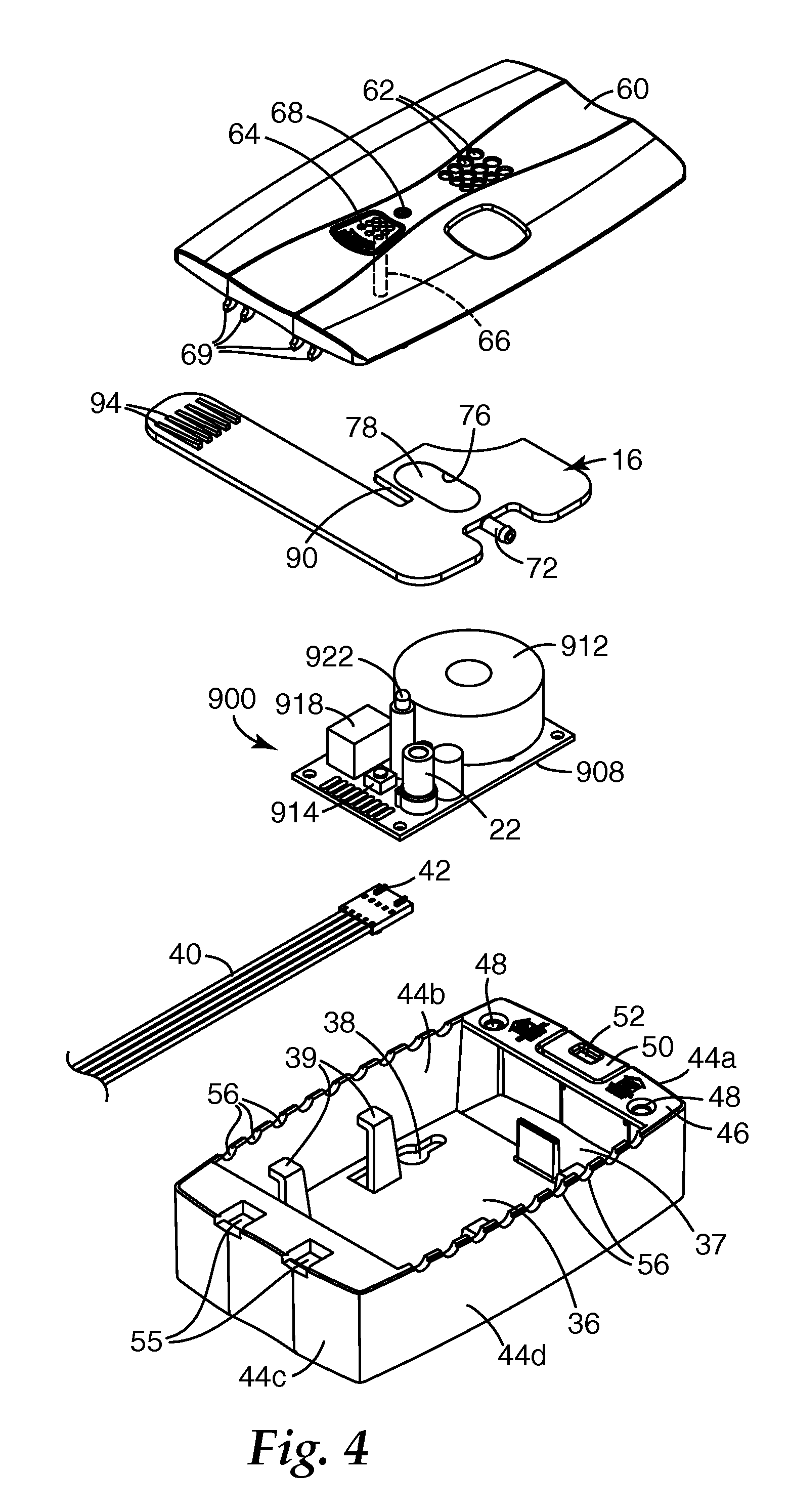
[0031]FIG. 1 is a schematic view of a gas monitoring system 10 of this invention operable for confirming performance of a carbon monoxide gas monitor apparatus 12. Included in the gas monitoring system 10 is a field test kit assembly 14. The field test kit assembly 14 includes a fluid coupling apparatus 16 also made according to this invention. The fluid coupling apparatus 16 is adapted to couple a source of testing gas, such as from a testing gas canis...


PUM

PropertyMeasurementUnit
threshold valueaaaaaaaaaa
time periodaaaaaaaaaa

Abstract

Method, apparatus, and system are utilized for testing the performance of a gas monitor against predetermined monitor characteristics to determine if performance of the gas monitor is validated in a manner whereby testing gas is directly delivered to the gas sensor.

Description

[0001]The present invention relates to gas testing processes, apparatus, and systems and, more particularly, to testing processes, apparatus, and systems for validating performance of gas monitors, such as carbon monoxide monitors.[0002]A variety of toxic gases are monitored for dangerous concentrations. One such gas is carbon monoxide, (CO), a colorless, tasteless, odorless, and deadly gas. CO in high concentrations is not only undetectable by humans but is also highly dangerous and widely prevalent in many everyday situations. For instance, carbon monoxide can be produced by combustion of a number of common household sources, including wood or gas fireplaces, gas or oil furnaces, wood stoves, gas appliances, etc. CO typically becomes unsafe when dangerous concentrations build-up due to, for example, poor ventilation. CO build-up is a potential problem, for example, in energy-efficient, airtight homes, vehicles, and plants that decrease the exchange of inside and outside air.[0003]...

Claims


Application Information

Patent Timeline
Patent Type & Authority Patents(United States)
IPC IPC(8): G01N7/00G12B13/00
CPCG01N33/007G01N33/004G01N2033/0072G01N33/0072
Inventor SCHEFFLER, ARTHUR
Owner AERIONICS
Learn More