Method and system for mesh-free analysis of general three-dimensional shell structures

a three-dimensional shell and analysis method technology, applied in the field of numerical simulation of the nonlinear structural behavior of a general three-dimensional (3d) shell structure, can solve the problems of computational cost, dramatic deterioration of accuracy, and inconvenient us

Active Publication Date: 2009-03-03
ANSYS INC
View PDF4 Cites 11 Cited by
  • Summary
  • Abstract
  • Description
  • Claims
  • Application Information

AI Technical Summary

Benefits of technology

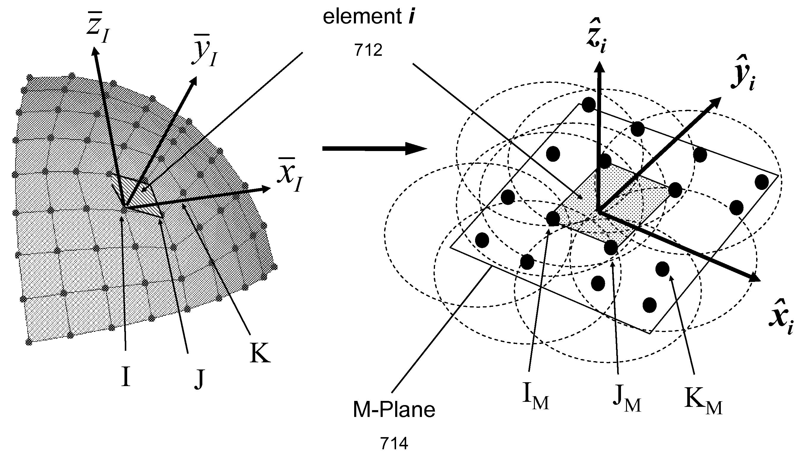
[0011]According to another aspect, the present invention further comprises: establishing a background mesh representing a reference surface describing the general shell structure, and mapping the reference surface onto the two-dimensional space based on one of the two particular schemes: a global projection that maps all elements of the background mesh in one projection operation based on minimization of angle distortion globally, and a local projection procedure that maps each element of the background mesh to the two-dimensional plane one at the time.

Problems solved by technology

Although FEA has been successfully applied to many fields to simulate various engineering problems, there are some instances that FEA may not be advantageous due to numerical compatibility condition is not the same as the physical compatibility condition of a continuum.
For example, in Lagrangian type of computations, one may experience mesh distortion, which can either end the computation altogether or result in dramatic deterioration of accuracy.
In addition, the FEA often requires a very fine mesh in problems with high gradients or a distinct local character, which can be computationally expensive.
Adaptive re-meshing procedures for simulations of impact / penetration problems, explosion / fragmentation problems, flow pass obstacles, and fluid-structure interaction problems etc., have become formidable tasks to undertake.
The difficulties here are not only re-meshing, but also mapping the state variables from the old mesh to the new mesh.
Hence, this process often introduces numerical errors; frequent re-mesh is not desirable.
Unfortunately, the mesh distortion still creates severe numerical errors for very large strain and high speed mechanical simulations.
In other cases, a mesh may carry inherent bias in numerical simulations, and its presence becomes a nuisance in computations.
An example is the strain localization problem, which is notorious for its mesh alignment sensitivity.
It is well known amongst the skilled in the art of engineering analysis that the mesh-free analysis would not be practical if the mesh-free analysis could only handle solid structures.

Method used


Image

  • Method and system for mesh-free analysis of general three-dimensional shell structures
  • Method and system for mesh-free analysis of general three-dimensional shell structures
  • Method and system for mesh-free analysis of general three-dimensional shell structures

Examples


Embodiment Construction

[0038]In the following description, numerous specific details are set forth in order to provide a thorough understanding of the present invention. However, it will become obvious to those skilled in the art that the present invention may be practiced without these specific details. The descriptions and representations herein are the common means used by those experienced or skilled in the art to most effectively convey the substance of their work to others skilled in the art. In other instances, well-known methods, procedures, components, and circuitry have not been described in detail to avoid unnecessarily obscuring aspects of the present invention.

[0039]Reference herein to “one embodiment” or “an embodiment” means that a particular feature, structure, or characteristic described in connection with the embodiment can be included in at least one embodiment of the invention. The appearances of the phrase “in one embodiment” in various places in the specification are not necessarily ...


PUM


Abstract

A method, system and computer program product pertained to engineering analysis of a general three-dimensional (3-D) shell structure using the mesh-free technique is disclosed. The structural responses are solved with mesh-free technique after the 3-D shell structure is mapped to a two-dimensional plane. According to one aspect, the present invention is a method for mesh-free analysis of a general three-dimensional shell structure, the method comprises: defining the general shell structure as a physical domain represented by a plurality of nodes in a three-dimensional space, creating a plurality of projected nodes by mapping the plurality of nodes in the three-dimensional space onto a two-dimensional plane, assigning a plurality of domain of influences, one for each of the plurality of projected nodes, and calculating a solution of the physical domain using a set of mathematical approximations pertaining to each of the plurality of projected nodes.

Description

BACKGROUND OF THE INVENTION[0001]1. Field of the Invention[0002]The present invention generally relates to method, system and computer program product used in engineering analysis, more particularly to numerical simulation of the non-linear structural behaviors of a general three-dimensional (3-D) shell structures based on mesh-free analysis.[0003]2. Description of the Related Art[0004]Finite element analysis (FEA) is a computerized method widely used in industry to model and solve engineering problems relating to complex systems since its invention in late 1950's. With the advent of the modern digital computer, FEA has been implemented as FEA computer program product. Basically, the FEA computer program product is provided with a model of the geometric description and the associated material properties at each point within the model. In this model, the geometry of the system under analysis is represented by solids, shells and beams of various sizes, which are called elements. The v...

Claims


Application Information

Patent Timeline
Patent Type & Authority Patents(United States)
IPC IPC(8): G06T17/00G06F17/10G06F7/60
CPCG06F17/5018G06F30/23
Inventor WU, CHENG-TANGGUO, YONG
Owner ANSYS INC
Why Eureka
Try Eureka