Compact two-beam push-pull free electron laser

Inactive Publication Date: 2009-03-03
JEFFERSON SCI ASSOCS LLC
View PDF11 Cites 3 Cited by
  • Summary
  • Abstract
  • Description
  • Claims
  • Application Information

AI Technical Summary

Benefits of technology

[0007]According to the present invention there is provided an ultra-compact free electron laser comprising a pair of opposed superconducting cavities that produce identical electron beams moving in opposite directions such that each set of superconducting cavities accelerates one electron beam and decelerates the other electron beam. Such an arrangement, allows the energy used to accelerate one beam to be recovered and used again to accelerate the second beam, thus, each electron beam is decelerated by a different structure than that which accelerated it so that energy exchange rather than recovery is achieved resulting in a more compact and highly efficient apparatus.

Problems solved by technology

While free electron lasers associated with large particle accelerators such as that at the Jefferson Laboratory in Newport News, Va. provide highly useful research tools, such devices, largely because of their cost and size are not widely available in, for example, universities or small research institutes.

Method used


Image

  • Compact two-beam push-pull free electron laser
  • Compact two-beam push-pull free electron laser

Examples


Embodiment Construction

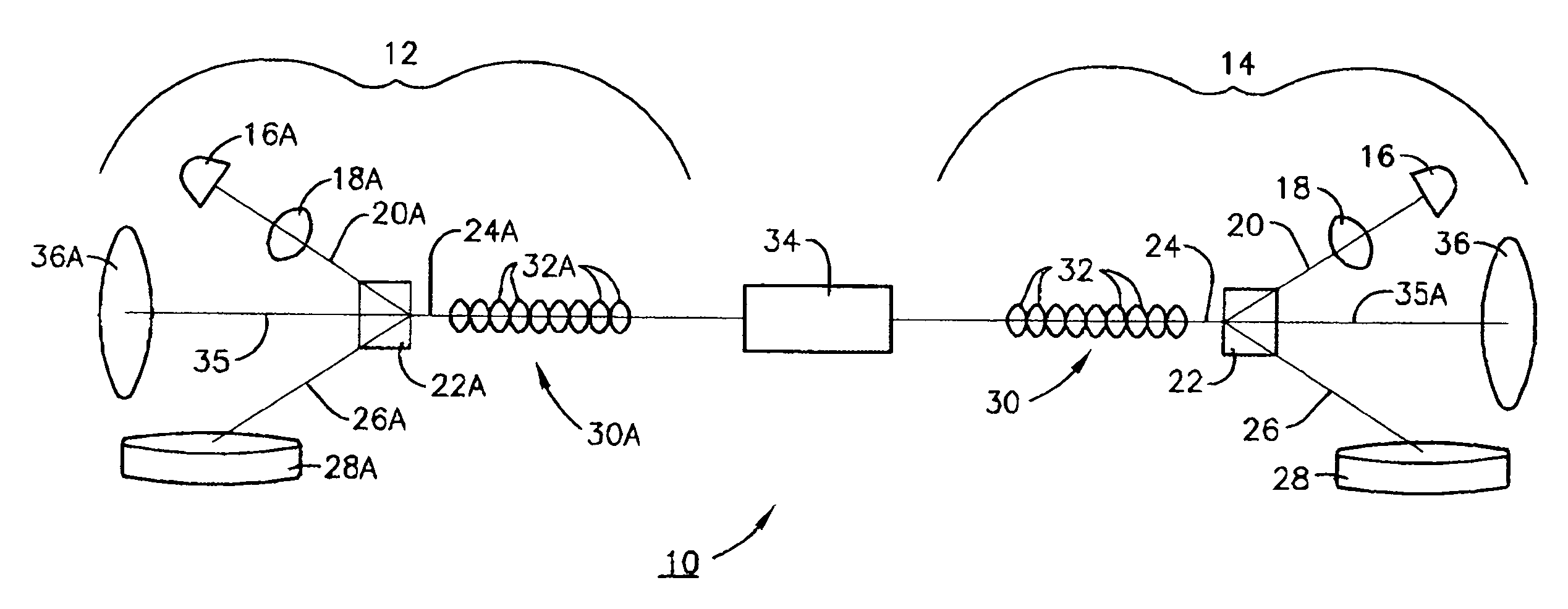
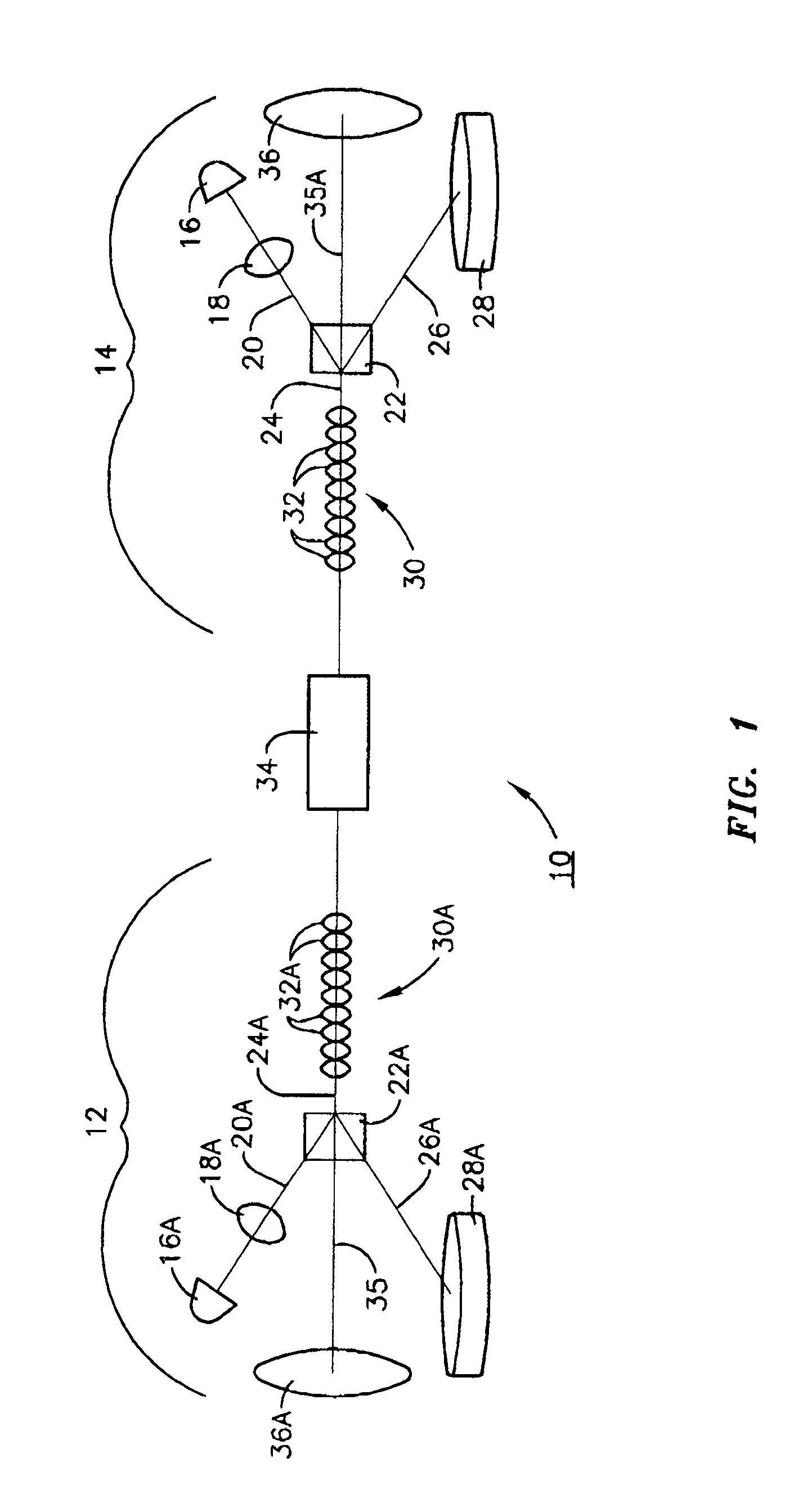
[0009]Referring now to the accompanying FIG. 1, as shown in that drawing, the compact free electron laser of the present invention 10 comprises a pair of opposed sets of electron generators 12 and 14, each comprising an electron injector or gun 16 and 16A that injects electron beams 20 and 20A into cryocavities 18 and 18A where separator or bend magnets 22 and 22A bring electron beams 20 and 20A onto acceleration axes 24 and 24A and also bend spent beams 26 and 26A to dumps 28 and 28A. It is important to note that bend magnets 22 and 22A must be designed to transport electrons with a large (˜50%) energy spread to the dump with very small losses. As used herein, the term “electron beam” is meant to be synonymous with the term “electron bunches” as the electron beam is comprised of electron bunches.

[0010]Electron beams 20 and 20A on acceleration axes 24 and 24A are introduced into cryomodules 30 and 30A comprising a series of superconducting cavities 32 and 32A and thence into wiggler...


PUM


Abstract

An ultra-compact free electron laser comprising a pair of opposed superconducting cavities that produce identical electron beams moving in opposite directions such that each set of superconducting cavities accelerates one electron beam and decelerates the other electron beam. Such an arrangement, allows the energy used to accelerate one beam to be recovered and used again to accelerate the second beam, thus, each electron beam is decelerated by a different structure than that which accelerated it so that energy exchange rather than recovery is achieved resulting in a more compact and highly efficient apparatus.

Description

[0001]The United States of America may have certain rights to this invention under Management and Operating Contract DE-AC05-060R23177 from the United States Department of Energy.FIELD OF THE INVENTION[0002]The present invention relates to free electron lasers and more particularly to such an ultra-compact such a device for the production of tunable coherent light in small free-standing laboratories.BACKGROUND OF THE INVENTION[0003]The energy recovered free electron laser (FEL) at Jefferson Laboratories in Newport News, Va. accelerates an electron beam in superconducting cavities and transfers it through a wiggler to produce light pulses and returns it to the beginning of the superconducting cavities at a phase that decelerates the beam so that energy is returned to the cavities. The light pulses from the wiggler are contained in an optical resonator (a pair of mirrors spaced a precise multiple of the bunch separation) that synchronously reflects the light back to the wiggler to a l...

Claims


Application Information

Patent Timeline
Patent Type & Authority Patents(United States)
IPC IPC(8): H01S3/00
CPCH01S3/0903H05H15/00
Inventor HUTTON, ANDREW
Owner JEFFERSON SCI ASSOCS LLC
Why Eureka
Try Eureka