Smear-limit based system and method for controlling vision systems for consistently accurate and high-speed inspection

a technology control system, applied in the field of strobe exposure time limit based system and method, can solve the problems of inability to reliably control or compare images and inspection results, inability to take advantage of the shorter minimum strobe exposure time and high motion speed, and general limitation of the maximum motion speed that may be used without excessive image smear. achieve the effect of increasing inspection throughput and being highly portabl

Active Publication Date: 2009-03-03
MITUTOYO CORP
View PDF8 Cites 16 Cited by
  • Summary
  • Abstract
  • Description
  • Claims
  • Application Information

AI Technical Summary

Benefits of technology

[0012]In step 1, a functional limit related to image smear is determined for the program. One example of such a functional limit is a “smear limit,” which is the amount of relative motion allowed between the camera and the workpiece during the effective image exposure time (e.g., strobe exposure time). The lesser the smear limit (i.e., the less the amount of relative motion that is allowed during exposure time), the less image smear, and hence the greater accuracy in inspection results. However, for a given strobe intensity and duration, the lesser the smear limit the slower the allowable relative motion speed between the camera and the workpiece, and hence the lesser inspection throughput.
[0025]In various exemplary embodiments, the method includes using continuous relative motion between the camera and the workpiece stage during image acquisition operations to increase inspection throughput. In various exemplary embodiments, one or more light sources of the machine vision inspection system include a light source strobing capability.
[0026]In summary, the present invention provides for a part program, which is highly portable and can run on various vision systems having different hardware capabilities, and that consistently provides a desired level of accuracy as well as optimum or near-optimum throughput, regardless of which vision system is used.

Problems solved by technology

For example, the maximum motion speed that may be used without excessive image smear is generally limited by the maximum power level and / or minimum exposure time of the strobe lighting system.
Thus, the resulting images and inspection results will not be reliably controlled or comparable.
A relatively poor solution to this problem is for the part program to specify a strobe exposure time and / or related motion speed that falls within the operating characteristics of any vision system that might be used.
However, this approach does not take advantage of the shorter minimum strobe exposure time and higher motion speed available with relatively high-capability vision systems, and will thus “arbitrarily” limit their potential throughput.

Method used


Image

  • Smear-limit based system and method for controlling vision systems for consistently accurate and high-speed inspection
  • Smear-limit based system and method for controlling vision systems for consistently accurate and high-speed inspection
  • Smear-limit based system and method for controlling vision systems for consistently accurate and high-speed inspection

Examples


Embodiment Construction

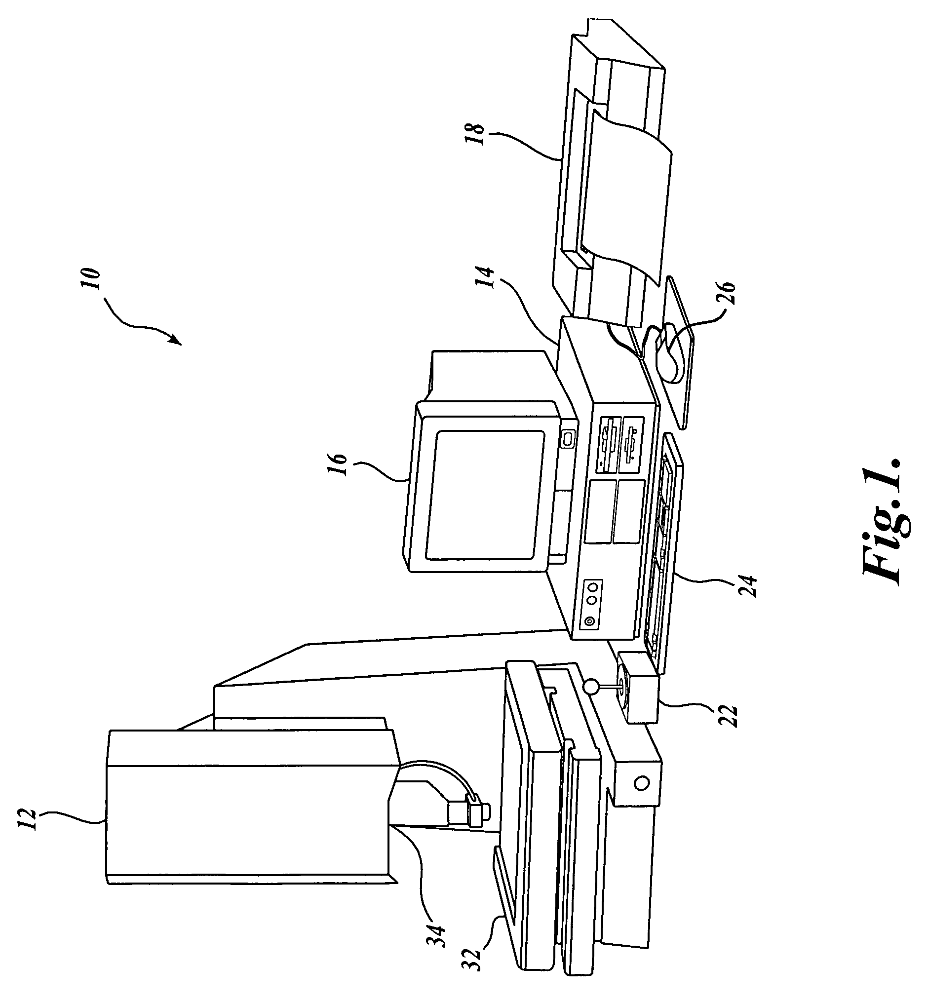
[0034]FIG. 1 is a block diagram of one exemplary machine vision inspection system 10 in accordance with the present invention. The machine vision inspection system 10 includes a vision measuring machine 12 that is operably connected to exchange data and control signals with a controlling computer system 14. The controlling computer system 14 is further operably connected to exchange data and control signals with a monitor 16, a printer 18, a joystick 22, a keyboard 24, and a mouse 26. The vision measuring machine 12 includes a moveable workpiece stage 32 and an optical imaging system 34 which may include a zoom lens or interchangeable lenses. The zoom lens or interchangeable lenses generally provide various magnifications for the images provided by the optical imaging system 34.

[0035]The joystick 22 can typically be used to control the movement of the movable workpiece stage 32 in both X and Y directions, which are generally parallel to the focal plane of the optical imaging system ...


PUM


Abstract

A machine vision inspection system and method for generating a workpiece image acquisition / inspection program, which can be shared by different machine vision systems having different hardware capabilities. Each system includes a movable stage for scanning and measuring selected workpiece features, and preferably includes strobe lighting to control the effective exposure time of the workpiece image. The program provides for the determination of various image acquisition parameters, such as the stage velocity, strobe light power, strobe exposure time, etc., based on a functional limit related to image smear. Thus, the program automatically adapts to any specific system, by allowing determination of optimal image acquisition parameters for that system based on the functional limit. Accordingly, the same program is usable on different systems to consistently provide a desired level of accuracy as well as optimum or near-optimum throughput, regardless of which vision system is used.

Description

FIELD OF THE INVENTION[0001]The invention relates generally to methods for programming and operating machine vision inspection systems having a camera and stage that are movable relative to one another in multiple directions so as to scan and inspect selected features of a workpiece on the stage. More particularly, it relates to systems and methods for creating a single computer script based on a functional limit related to image smear, such that the script operates reliably to achieve high levels of inspection accuracy and speed on a variety of machine vision inspection systems that have differing operating specifications.BACKGROUND OF THE INVENTION[0002]Precision machine vision inspection systems (or “vision systems” in short) can be utilized to obtain precise dimensional measurements of inspected objects and to inspect various other object characteristics. Such systems may include a computer, a camera and optical system, and a precision stage that is movable in multiple direction...

Claims


Application Information

Patent Timeline
Patent Type & Authority Patents(United States)
IPC IPC(8): G06K9/00
CPCG01N21/8806H04N5/2354H04N23/74
Inventor DELANEY, MARK L.
Owner MITUTOYO CORP
Why Eureka
Try Eureka