Mouth rinsing device having two detachably connectable housings

a technology of detachable housings and rising devices, which is applied in the direction of piston pumps, carpet cleaners, instruments, etc., can solve the problems of difficult to grasp the relative thick structure and damage to the riser tube, and achieve the effect of easy holding

Inactive Publication Date: 2009-03-10
GIMELLI LAB
View PDF27 Cites 136 Cited by
  • Summary
  • Abstract
  • Description
  • Claims
  • Application Information

AI Technical Summary

Benefits of technology

[0003]An object of the present invention, therefore, is to provide a mouth rinsing ...

Problems solved by technology

On the one hand, the parallel configuration of pump housing and reservoir results in a relatively thick structure that is difficult to grasp.
On t...

Method used


Image

  • Mouth rinsing device having two detachably connectable housings
  • Mouth rinsing device having two detachably connectable housings
  • Mouth rinsing device having two detachably connectable housings

Examples


Embodiment Construction

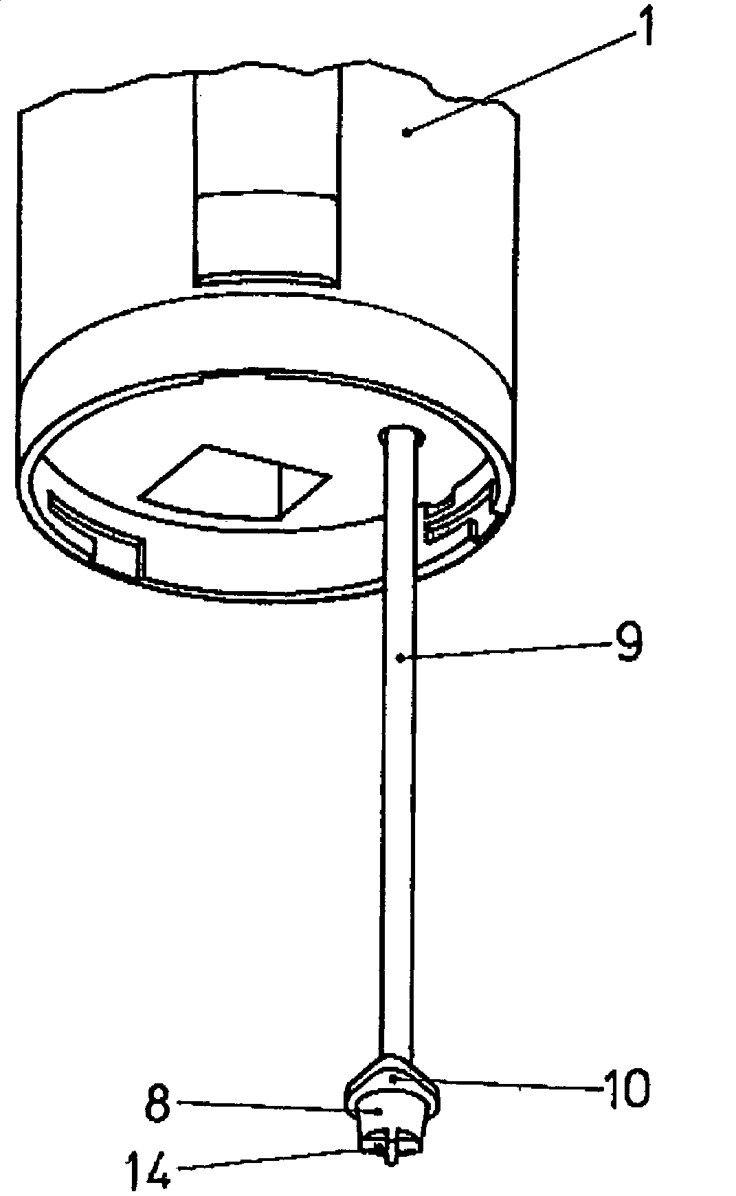
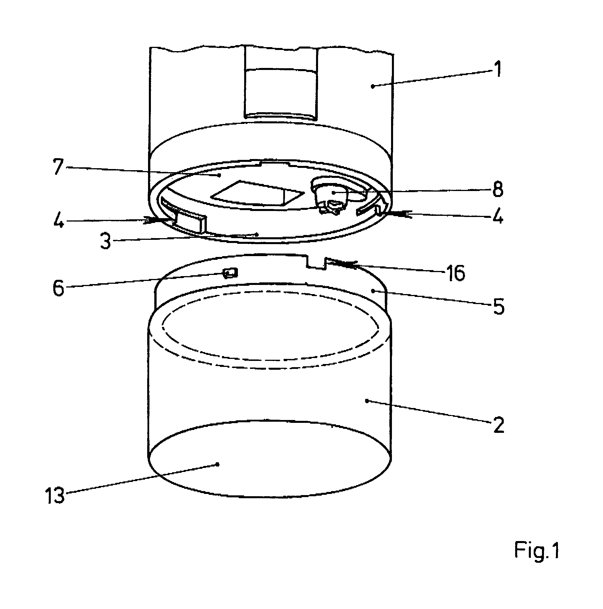
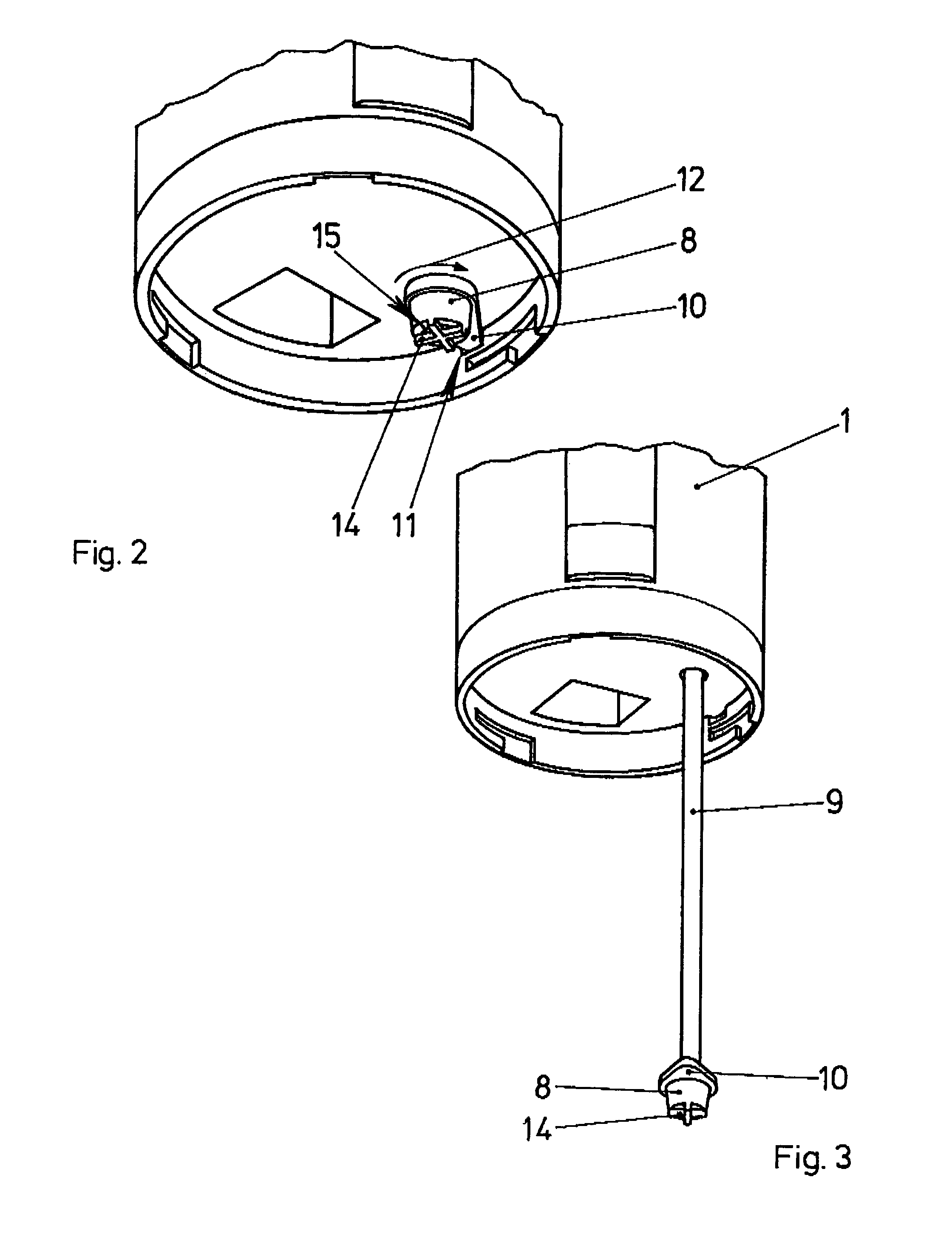
[0023]The upper half of FIG. 1 shows the lower part of a cylindrical pump housing 1. An electric motor pump and batteries, or rechargeable batteries (not illustrated here in greater detail) for driving the motor are located in the pump housing 1. A likewise cylindrical water reservoir 2 having the same external diameter is located on the underside, so that the two housings fit flush into one another and form a housing for a mouth rinsing device having a continuous cylindrical shape.

[0024]For connecting the pump housing 1 to the reservoir 2 the pump housing 1 has a circumferential ridge 3, on the inside of which are located three slots 4 for bayonet locks.

[0025]The upper edge 5 of the reservoir 2 is inwardly recessed in a step-like manner so as to allow insertion into the opening formed by the ridge 3. On the exterior of the edge 5 slot pins 6 are located which are inserted into the slots 4, whereby a rotation of the reservoir 2 about its longitudinal axis introduces the slot pins 6 ...


PUM


Abstract

A mouth rinsing device comprising a pump housing and a reservoir. These two housings are arranged in series; i.e., the reservoir is attached to the base of the pump housing. A riser tube having a head on its end is situated on the pump housing and is fixed there by means of a lock so that only the head protrudes. When the reservoir is attached the lock is simultaneously released, so that the riser tube is able to slide into the reservoir and the intake opening is situated just above the base. After the reservoir is removed, the riser tube may be pushed in again manually. The riser tube is subsequently fixed in the retracted position by locking the head to the base of the pump housing.

Description

BACKGROUND OF THE INVENTION[0001]This invention relates to a mouth rinsing device and , more particularly, this invention relates to a mouth rising device having two detachably connectable housings, the first housing being a pump housing having in its interior at least one pump and a water outlet nozzle on the upper end, and the second housing forming a water reservoir and the pump being connected to a riser tube terminating above the base of the reservoir.[0002]Such a mouth rinsing device is known from DE 195 25 738, for example: a water outlet nozzle is located at the upper end of a slender pump housing, below which a pump is situated in the pump housing, and further below an electric motor for driving the pump, and, lastly, at the base of the pump housing, a battery for supplying power to the pump. Next to the pump housing is located a second housing which forms a water reservoir and which extends practically over the entire length of the pump housing and is detachably connected ...

Claims


Application Information

Patent Timeline
IPC IPC(8): B67D5/60B67D7/78A61C17/02B05B15/00B05B15/30
CPCA61C17/02B05B9/0861B05B15/005B05B15/30
Inventor SCHUTZ, ALFRED
Owner GIMELLI LAB
Why Eureka
Try Eureka