System with lifting columns

a technology of lifting columns and lifting frames, applied in the direction of lifting frames, lifting devices, load transportation vehicles, etc., can solve the problems of affecting the safety of workers, coupling damage, and workshop floor interruption, so as to reduce the need for cables

Active Publication Date: 2009-03-10
STERTIL
View PDF10 Cites 58 Cited by
  • Summary
  • Abstract
  • Description
  • Claims
  • Application Information

AI Technical Summary

Benefits of technology

[0010]The lifting columns in a sub-group are preselected (prior to handling a vehicle or object). Use can be made for this purpose of a master column which can be chosen at random from the available group of lifting columns, or a predetermined number of master columns, which are identifiable as such, can be provided in the system. The other lifting columns of the group can then be designated as slave columns. In one embodiment with identifiable predetermined master columns, the number of sub-groups is determined by the number of master columns. In other embodiments, wherein a lifting column to be chosen at random from the group can be used as master column, as many sub-groups can be formed as there are lifting columns in the group, or the sub-group can include all lifting columns of the group itself. It will be apparent that a high degree of flexibility can be hereby achieved.
[0012]Also, since in such a system usually more than one slave is employed, starting the selection process with the master is convenient and reduces complexity thereafter. The other lifting columns are then automatically, upon their selection, slaves and will identify themselves as such, and their availability for selection, to the master. The order in which the remaining lifting columns, that are required for the sub-group and the application of that sub-group, sign-on to the sub-group in general, and identify themselves to the master, can favourably be employed to also assign an address to these lifting columns.
[0015]The selection means of a selected master column are preferably adapted to transmit a delete signal, at the beginning of a new selection of at least one slave column, to at least that lifting column or those lifting columns which was or were selected with the relevant master column in a sub-group at an earlier stage, in order to cancel the previous selection thereof. In this way a lifting column which has functioned earlier with the relevant master column in a sub-group is prevented from continuing to respond to lifting instructions in a new sub-group with this—or any other—master column therein.

Problems solved by technology

Also, the cables from, to and between the lifting columns are often in the way on the workshop floor, wherein people can trip over them, which can cause a hazardous situation.
The couplings can be damaged as a result of frequent disconnection of the cabling for a new setup or because of the danger of someone stumbling over the cables and thereby disconnecting the cables, after which the cables have to be replaced and work on the workshop floor has to be interrupted until new cables are in place.
When couplings are damaged or couplings which have merely been pulled out, failure of the system could occur which could then in turn result in a hazardous situation for the users of the system.
Without the sockets of a cable based system, assigning an address or identification to a desired one of the lifting columns is a severe problem, that is according to the disclosure of WO 92 / 19.527 avoided with a system comprising a group of a fixed number of predetermined lifting columns.

Method used


Image

  • System with lifting columns
  • System with lifting columns
  • System with lifting columns

Examples


Embodiment Construction

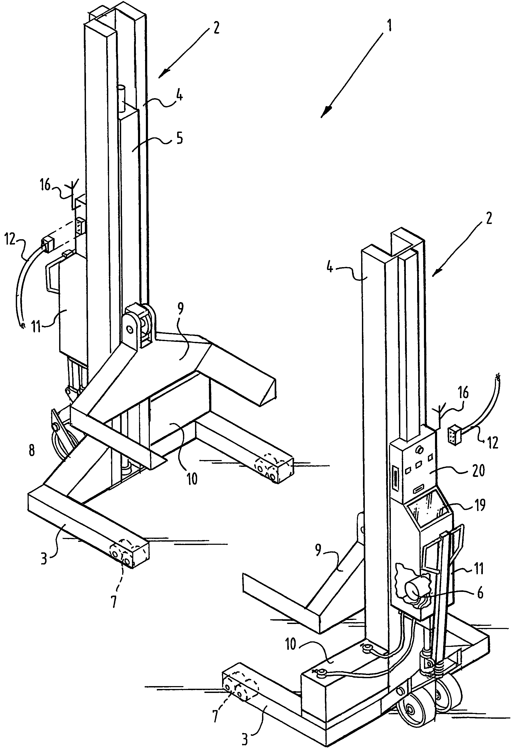
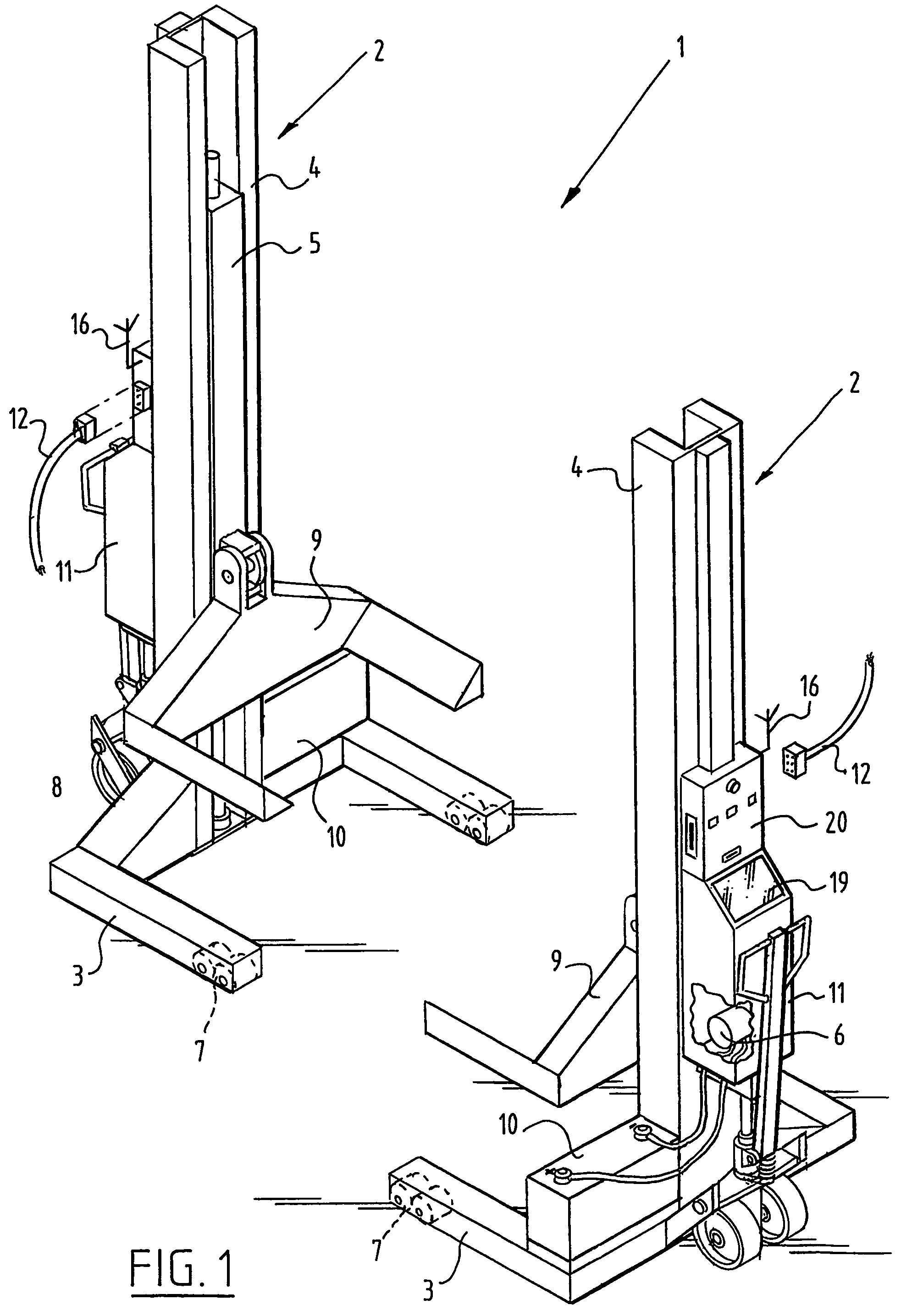
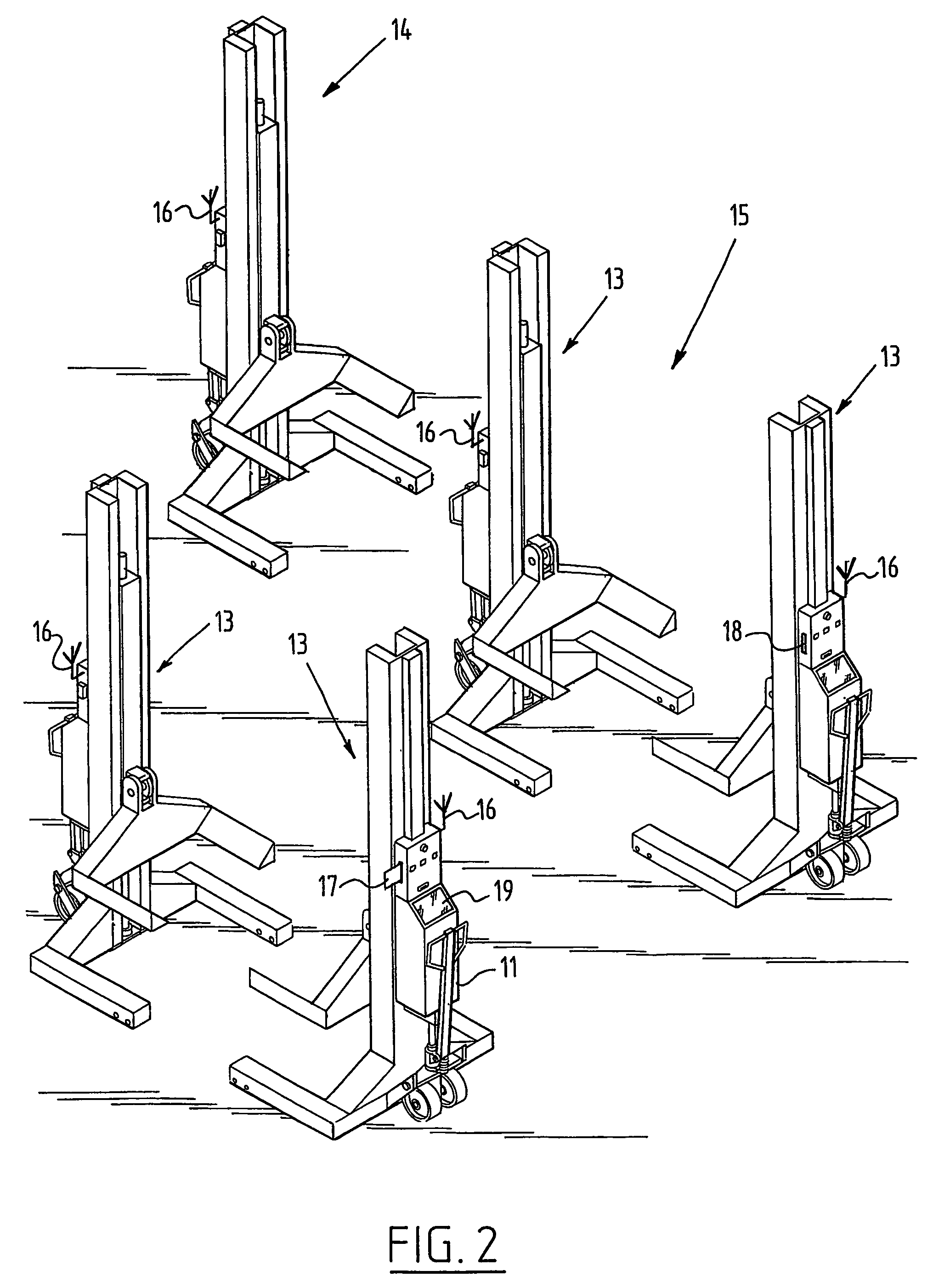
[0025]FIG. 1 shows a system 1 according to the present invention which comprises two lifting columns 2. Each of the lifting columns is provided with a foot 3 and a mast part 4, wherein a carriage 5 is movable up and downward along mast part 4 under the influence of a drive in the form of a motor 6.

[0026]Foot 3 and mast part 4 thus form a kind of frame which can travel over rollers 7 and wheels 8. Wheels 8 can be raised per se along the frame, whereby the foot comes to lie on the ground and there is no danger of the lifting column 2 being able to move away while it is bearing a load.

[0027]Arranged on carriage 5 is a carrier 9 which is designed to engage for instance a wheel of a vehicle (not shown).

[0028]As already noted, movement of carriage 5 and the related carrier 9 is caused by a motor 6, in particular an electric motor, which is provided with electric power by a battery 10. Battery 10 is a source of energy not only for electric motor 6, but also for a control (not shown) accomm...


PUM


Abstract

A system is for lifting and lowering an object, such as a vehicle. Such a system includes at least two mobile lifting columns with: a displaceable frame with a standing mast part; a carrier displaceable along the mast part for engaging the object to be lifted; a drive for moving the carrier along the mast part; a control for controlling at least the drive; and communication devices for communicating with at least other lifting columns in the group via a transmission or broadcast path. Further, at least one of the lifting columns in the group includes a selectively user operable selection device for, when actuated, selecting any of the lifting columns from the group for a sub-group. As such, a higher degree of flexibility is provided.

Description

[0001]This application is the national phase under 35 U.S.C. § 371 of PCT International Application No. PCT / NL2003 / 000638 which has an International filing date of Sep. 15, 2003, which designated the United States of America and which claims priority on Netherlands Patent Application number NL 1021448 filed Sep. 13, 2002, the entire contents of which are hereby incorporated herein by reference.FIELD OF THE INVENTION[0002]The present invention generally relates to a system with lifting columns for lifting and lowering an object, such as a vehicle, and more particularly a car, bus, truck or the like.BACKGROUND OF THE INVENTION[0003]In the systems, that are known from e.g. U.S. Pat. No. 6,315,079, the lifting columns are disposed displaceably on a workshop floor, and over the workshop floor are arranged the cables that are required for electric power supply to the drive and control of the lifting columns, as well as conductors for mutual contact between the controls of the individual l...

Claims


Application Information

Patent Timeline
Patent Type & Authority Patents(United States)
IPC IPC(8): B66F3/46
CPCB66F3/46
Inventor BERENDS, JANDELL AMORE, JEANDE JONG, JURJEN JAN
Owner STERTIL
Why Eureka
Try Eureka