Grinding apparatus and grinding system

a technology of grinding apparatus and grinding system, which is applied in the direction of grinding heads, edge grinding machines, manufacturing tools, etc., can solve the problems of not applying the desired polishing force to the metal rings, and achieve the effect of reducing grinding force, efficient grinding, and prolonging grinding tim

Active Publication Date: 2009-03-10
TOYOTA JIDOSHA KK
View PDF8 Cites 15 Cited by
  • Summary
  • Abstract
  • Description
  • Claims
  • Application Information

AI Technical Summary

Benefits of technology

[0008]In view of the foregoing problems, it is an object of the invention to provide a grinding apparatus and a grinding system that do not require any jigs for preventing the falling of the metal belt, and that are capable of preventing the formation of burrs or droops on the edge surface of the metal belt, or providing a corner of the edge surface with an R, even when the length of the metal belt is changed. It is another object of the invention to provide a grinding system capable of efficiently grinding the belt edge surface while eliminating the problem of the polishing brush being bent in one direction and without damaging the surface of the belt.
[0036]In accordance with the invention, the direction of rotation of the two rotating bodies (first rotating body and second rotating body) in each grinding apparatus is reversed from one belt to another. If the direction of rotation of the rotating bodies were to be reversed during the processing of each belt, such reversal from forward rotation to backward rotation, for example, would take an additional time for acceleration and deceleration of the rotating bodies, possibly extending the grinding time. On the other hand, if the direction of rotation of the individual rotating bodies were to be fixed in one direction, the brushes would develop a tendency to flow in one direction, resulting in a decrease in grinding force. Thus, in accordance with the invention, instead of reversing the direction of rotation of the rotating bodies in each belt, the rotation direction of the rotating bodies is changed from one belt to another. In this way, the acceleration and deceleration time for the rotating bodies can be eliminated, whereby efficient grinding can be performed and the brushes can be prevented from acquiring any directional tendencies.

Problems solved by technology

However, the metal rings are pushed and caused to fall in the direction in which the polishing brush enters toward the metal rings, thereby failing to apply a desired polishing force to the metal rings.

Method used


Image

  • Grinding apparatus and grinding system
  • Grinding apparatus and grinding system
  • Grinding apparatus and grinding system

Examples


Embodiment Construction

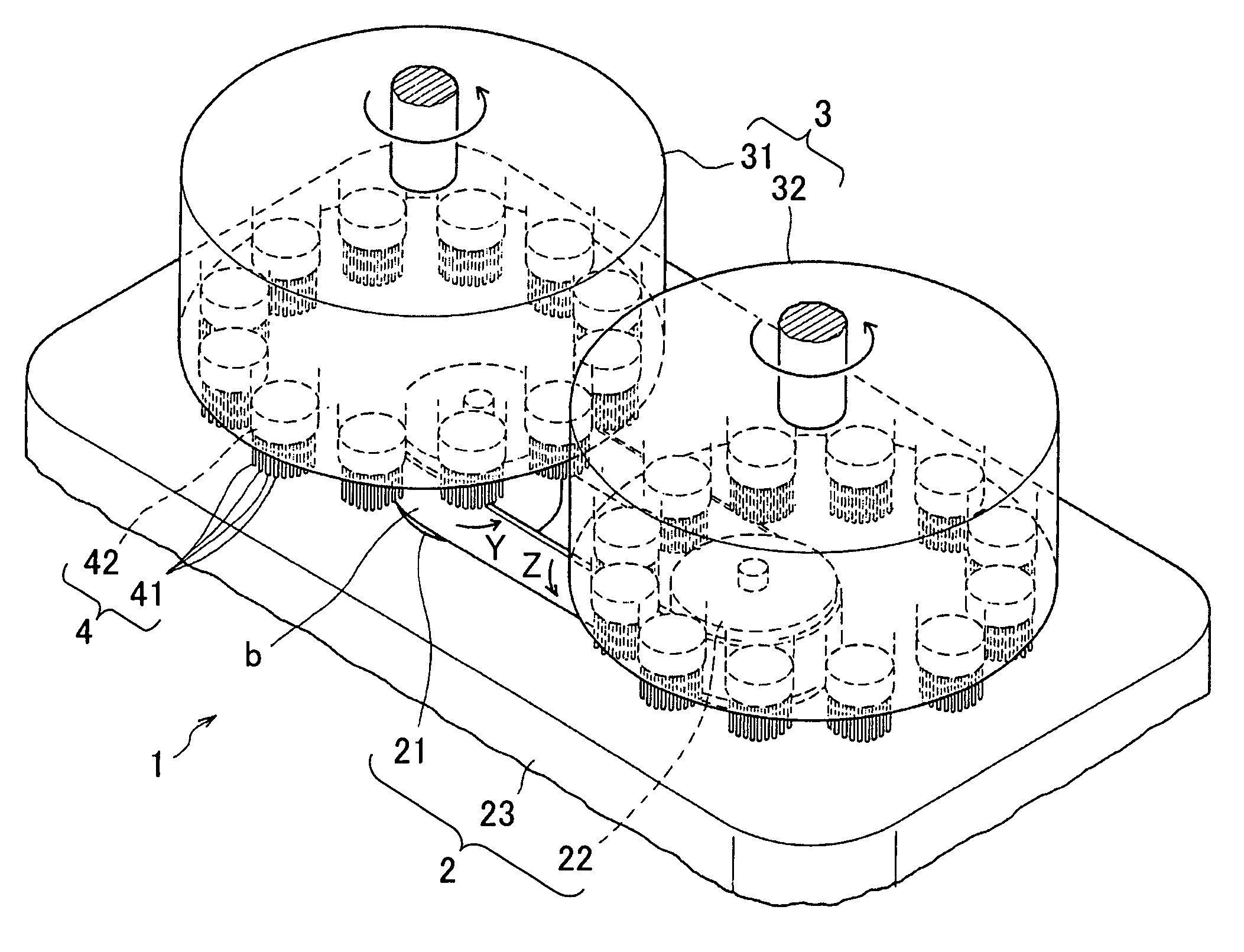
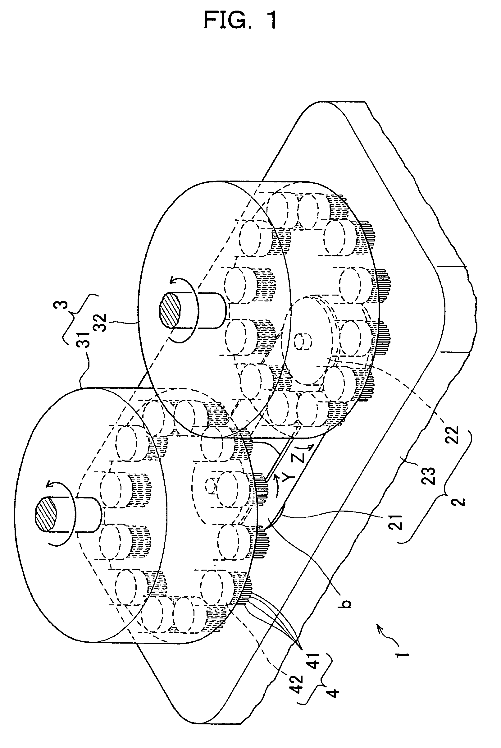
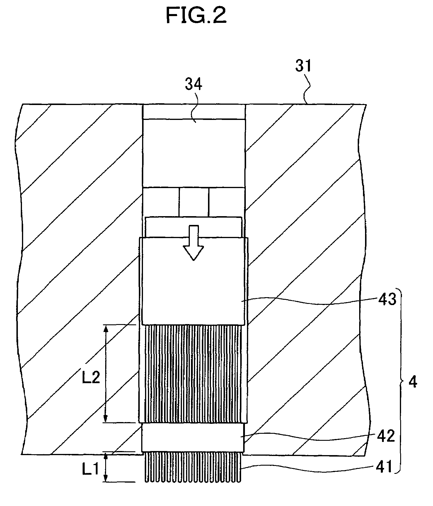
[0057]Embodiments of the invention will be described in the following with reference to the drawings. FIG. 1 shows a perspective view of a grinding apparatus according to the invention. FIG. 2 shows a vertical sectional view of a segment brush. FIGS. 3, 5, 7, 9, 11, 13, and 15 are plan views sequentially illustrating the operation of the grinding system. FIGS. 4, 6, 8, 10, 12, 14, and 16 are arrow views of FIGS. 3, 5, 7, 9, 11, 13, and 15, respectively. FIG. 17 shows a time history waveform during rotation control of a rotating body in the grinding apparatus. FIG. 17(a) shows a conventional time history waveform, while FIG. 17(b) shows a time history waveform according to the invention. In the illustrated embodiments, a metal belt (having a burr on the edge or an oxide film formed on the surface) is ground for a CVT belt. However, it goes without saying that the object to be ground is not limited to such metal belt.

[0058]A grinding apparatus 1 is comprised of, as shown in FIG. 1, a ...


PUM

PropertyMeasurementUnit
thicknessaaaaaaaaaa
incident angleaaaaaaaaaa
withdrawal angleaaaaaaaaaa

Abstract

A grinding apparatus and a grinding system capable of efficient and superior grinding performance prevent the falling of a belt during the grinding of an edge surface thereof. The apparatus includes two rotating bodies 31 and 32 each having segment brushes 4, 4, . . . attached in the circumferential direction at the edge thereof. The rotating bodies 31 and 32 are rotated in the same direction. The tip of the segment brushes 4, 4, . . . is opposed to one edge surface of a belt b stretched between a driving roller 21 and a driven roller 22. The segment brushes 4 of the two rotating bodies enter toward the belt b at appropriate locations on the one edge surface, such that the falling of the belt can be prevented. A grinding apparatus 1 includes a grinder 3 consisting of the rotating bodies 31 and 32, and a holder consisting of the rollers 21 and 22 and a casing 23 by which the rollers are rotatably supported. A plurality of such grinding apparatuses 1 are disposed at regular intervals, whereby a grinding system 10 is constructed.

Description

TECHNICAL FIELD[0001]The present invention relates to a grinding apparatus for grinding an edge surface of a belt stretched between two rollers, and to a grinding system including a plurality of such grinding apparatuses. Particularly, the invention relates to a grinding apparatus and a grinding system capable of efficient and superior grinding performance by preventing the falling of the belt during the grinding of the belt edge surface.BACKGROUND ART[0002]A metal CVT belt for high load transmission used in a continuously variable transmission (CVT) is formed of belt stacks each consisting of circular belts, the belt stacks being arranged in the width direction of the belt. The belt stacks are each locked and fastened with a plurality of blocks (elements). For example, as shown in FIG. 18a, circular belts a, a, . . . are stacked to form a stack b, and such stacks b, b are fitted in a plurality of blocks c, c, . . . to form a CVT belt d. The circular belt a is formed as follows. Edg...

Claims


Application Information

Patent Timeline
Patent Type & Authority Patents(United States)
IPC IPC(8): B24B1/00
CPCB24B7/12B24B9/04B24B29/005B24B41/047
Inventor IGA, KIYOSHI
Owner TOYOTA JIDOSHA KK
Why Eureka
Try Eureka