
Arrangement for regulating the temperature of the sample space of a microscope

a technology for regulating the temperature of the sample space and the arrangement of the sample space, which is applied in the direction of microscopes, optics, instruments, etc., can solve the problems of large amount of energy and time required for changing the temperature, and the inability to maintain the desired temperature or temperature constancy at the sample location regulating resources, so as to reduce the thermal mass of the elements without a large expenditure on the arrangement

Active Publication Date: 2009-03-10
CARL ZEISS MICROSCOPY GMBH
View PDF10 Cites 4 Cited by
  • Summary
  • Abstract
  • Description
  • Claims
  • Application Information

AI Technical Summary

Benefits of technology

The invention is about improving the temperature control of a microscope's sample space. The goal is to reach the desired temperature at the front lens of the objective without needing a costly arrangement. The invention achieves this by using a structural component, such as an insulating ring, to block the heating or cooling flow between the objective and the objective turret. This results in a reduction of the thermal mass, allowing for easier temperature changes at the sample location. Overall, the invention improves the efficiency and accuracy of microscope temperature control.

Problems solved by technology

All of the known solutions have the disadvantage that the amount of heat or cold which flows off in the areas remote of the front lens and even in the objective turret is so large that it is impossible to maintain a desired temperature or temperature constancy at the sample location without a very high expenditure with respect to the arrangement and regulating resources.
Further, the thermal mass of the elements is very large so that a large amount of energy and time is required for changing the temperature.

Method used


Image

  • Arrangement for regulating the temperature of the sample space of a microscope
  • Arrangement for regulating the temperature of the sample space of a microscope
  • Arrangement for regulating the temperature of the sample space of a microscope

Examples


Embodiment Construction

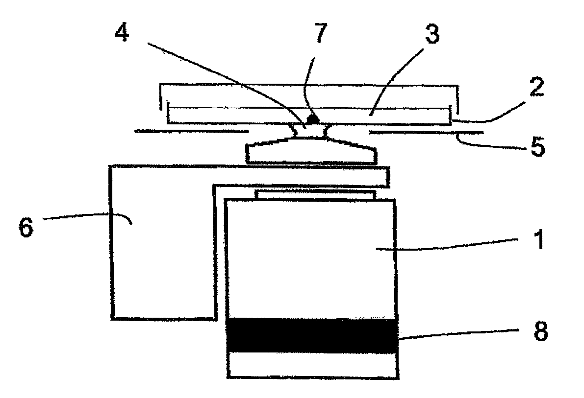
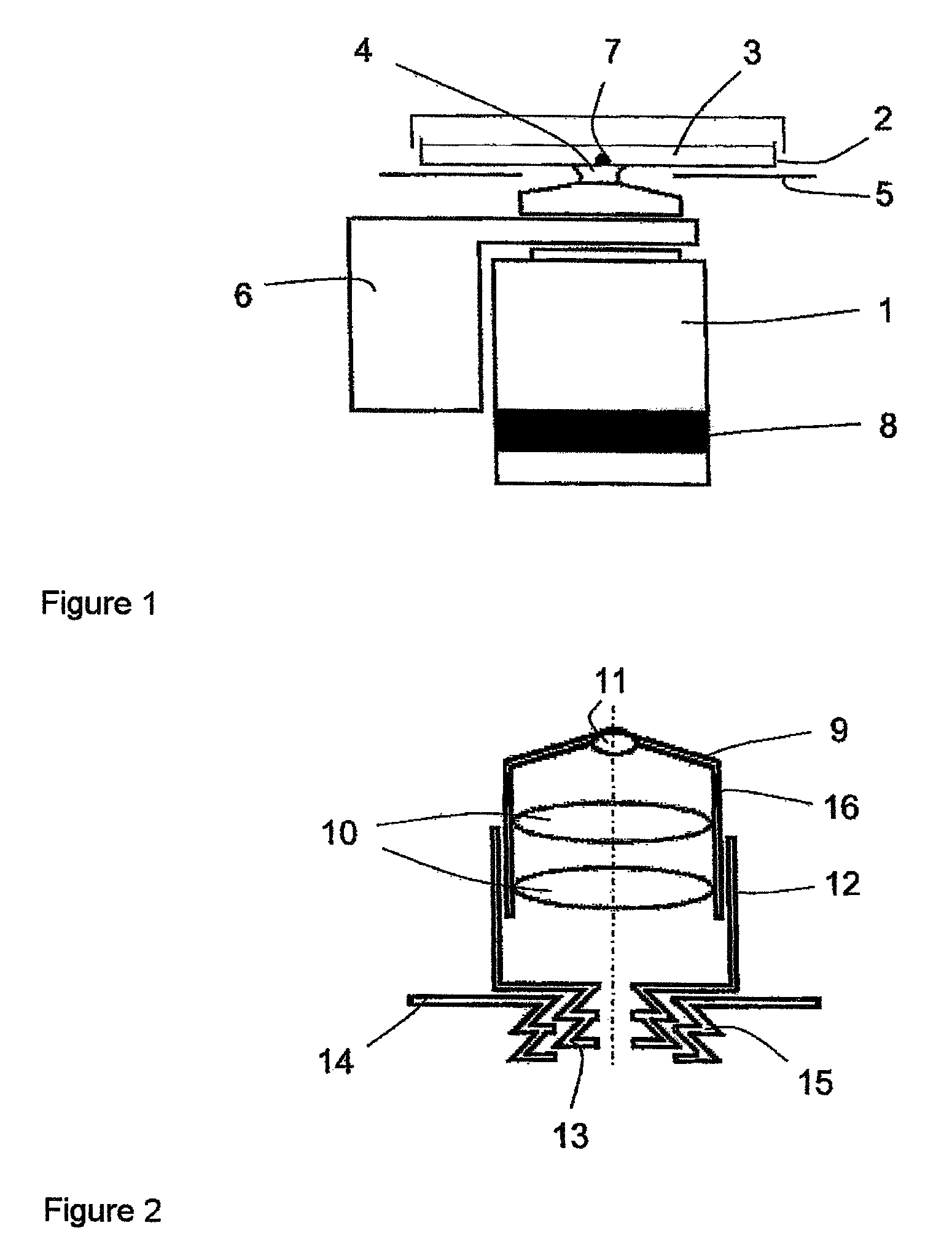
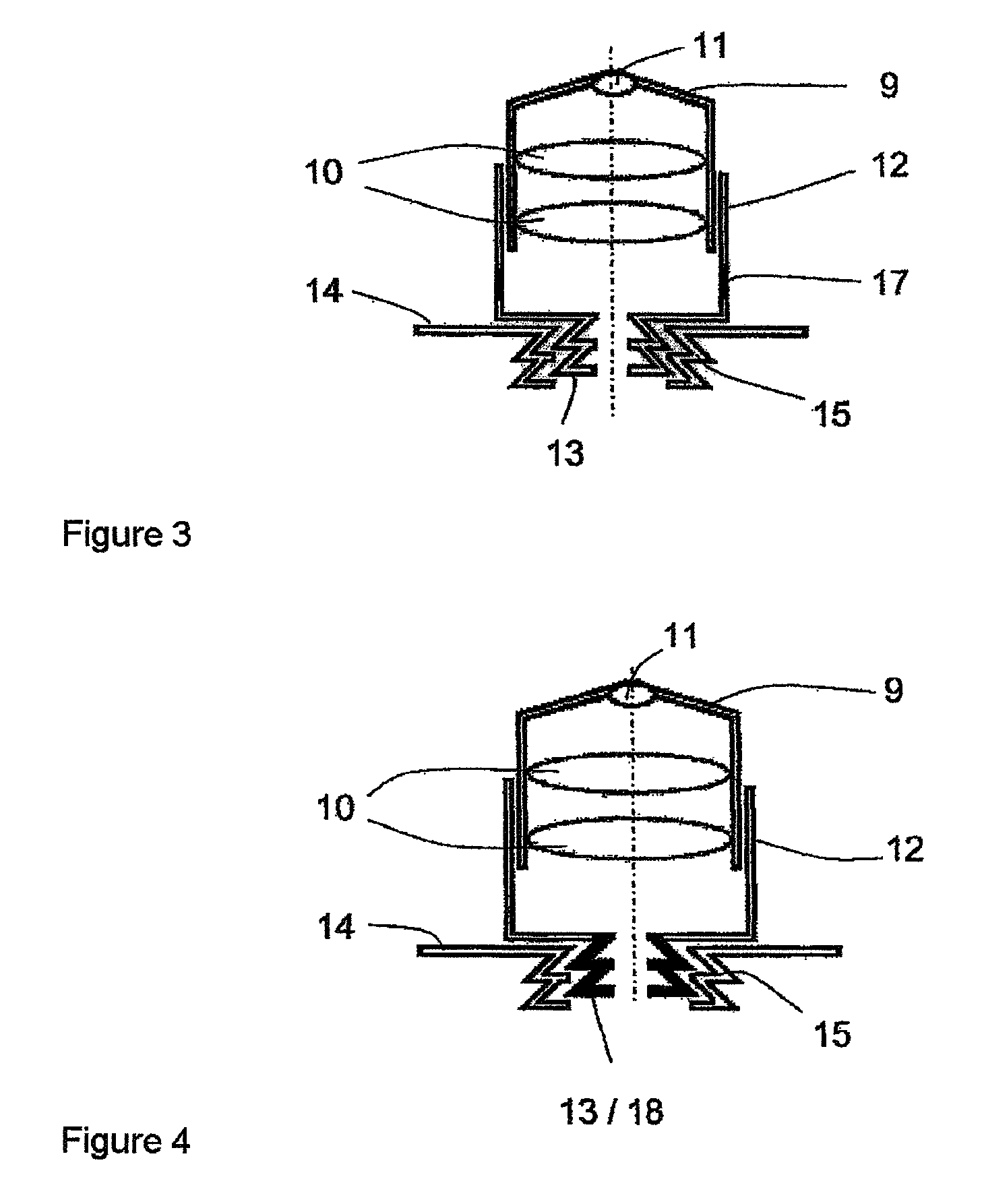
[0023]As stated above, the invention comprises an arrangement for regulating the temperature of the sample space at a microscope of the type described above in that at least one structural component part which blocks the heating flow or cooling flow is arranged between the objective heating element or objective cooling element and the objective turret and is advantageously constructed as a self-enclosed insulating ring comprising a material having almost no thermal conductivity.

[0024]The arrangement can be used in both upright and inverted microscopes. It is irrelevant whether the flow to be blocked is a heating flow or a cooling flow.

[0025]As a result of the arrangement of the structural component part blocking the heating flow or cooling flow, the heating flow or cooling flow generated by the objective heating element or objective cooling element is interrupted by the objective in the objective turret. The desired temperature at the front lens of the objective and, therefore, in t...


PUM


Abstract

The invention is directed to an arrangement for regulating the temperature of the sample space of a microscope, preferably for observing cells (live cell imaging) with an objective turret carrying objectives, a sample holder serving to receive a sample, a heating or cooling insert with an incubator hood for managing the temperature of the sample holder, and an objective heating element or objective cooling element. According to the invention, at least one structural component part which blocks the heating flow or cooling flow is provided between the objective heating element or objective cooling element and the objective turret.

Description

CROSS-REFERENCE TO RELATED APPLICATIONS[0001]This application claims priority of German Application No. 10 2006 034 534.7, filed Jul. 26, 2006, the complete disclosure of which is hereby incorporated by reference.BACKGROUND OF THE INVENTION[0002]a) Field of the Invention[0003]The invention is directed to an arrangement for regulating the temperature of the sample space of a microscope, preferably for observing living cells (live cell imaging) with an objective turret carrying objectives, a sample holder serving to receive a sample, a heating or cooling insert with an incubator hood for managing the temperature of the sample holder, and an objective heating element or objective cooling element.[0004]b) Description of the Related Art[0005]In microscopic examination of living cells or tissue portions, it is increasingly required to adjust the specific living conditions of the specimen. Apart from taking into account the relative air humidity and the CO2 (carbon dioxide) content, this a...

Claims


Application Information

Patent Timeline
Patent Type & Authority Patents(United States)
IPC IPC(8): G02B21/26
CPCG02B21/28G02B21/30B01L7/00
Inventor WEHNER, EUGENSCHAFFER, JOERGKLEINSCHMIDT, WERNER
Owner CARL ZEISS MICROSCOPY GMBH
Learn More